Apparatus and method for enhancing dynamic range of charge coupled device-based spectrograph

a technology of charge coupled device and spectrograph, which is applied in the field of optical imaging, can solve the problems of preventing the use of spectrographs in some demanding applications, performance limitations of available detector arrays, and dynamic range limitation,

Inactive Publication Date: 2005-01-06
VERITY INSTR
View PDF8 Cites 35 Cited by
  • Summary
  • Abstract
  • Description
  • Claims
  • Application Information

AI Technical Summary

Problems solved by technology

Nevertheless, performance limitations of available detector arrays often prevent the use of spectrographs in some demanding applications.
One important limitation is dynamic range.
The limitation to dynamic range in a CCD-based spectrograph exists because there is a limit to the amount of charge that each pixel and each horizontal shift register can hold.
Inaccurate measurements result if the charge accumulated in any pixel, or any shift register, reaches this saturation level.
By contrast, several noise sources exist in the readout process which cause inherent uncertainty in the measurement of the charge in any shift register.
A problem occurs if the spectrum of interest includes regions of widely differing intensity, since there may be no single integration ti...

Method used


Image

  • Apparatus and method for enhancing dynamic range of charge coupled device-based spectrograph
  • Apparatus and method for enhancing dynamic range of charge coupled device-based spectrograph
  • Apparatus and method for enhancing dynamic range of charge coupled device-based spectrograph

Examples


Embodiment Construction

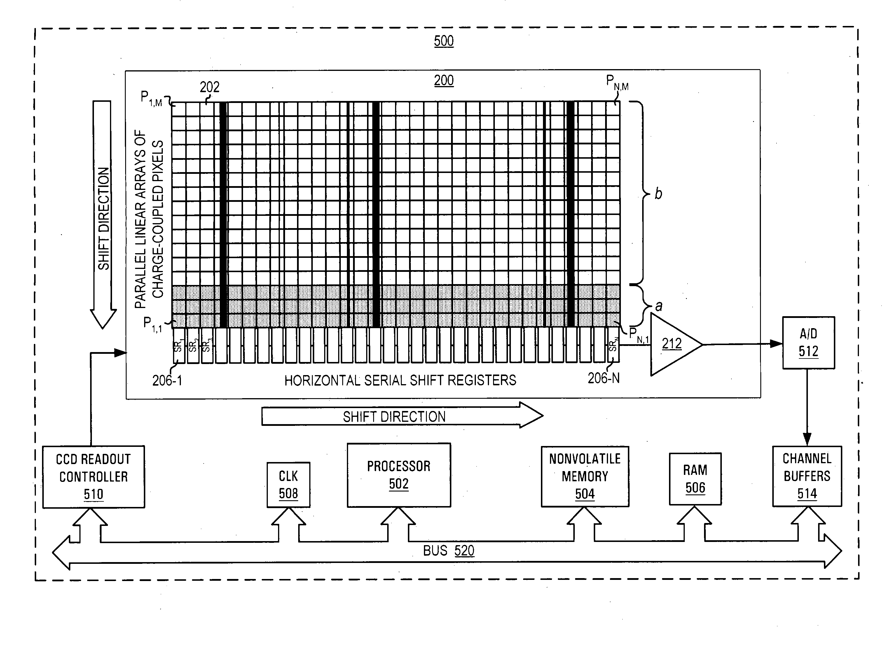
The invention being disclosed here is a spectrograph consisting of an optical dispersing and imaging system, a CCD for light detection, and a data processor. The CCD employs a heretofore unknown pixel binning method, the “two-region line binning mode,” for increasing the dynamic range over what can be achieved in the conventional line binning mode. The data processor converts the electrical signals produced in this method to a numerical or graphical representation of the light's intensity as a function of wavelength.

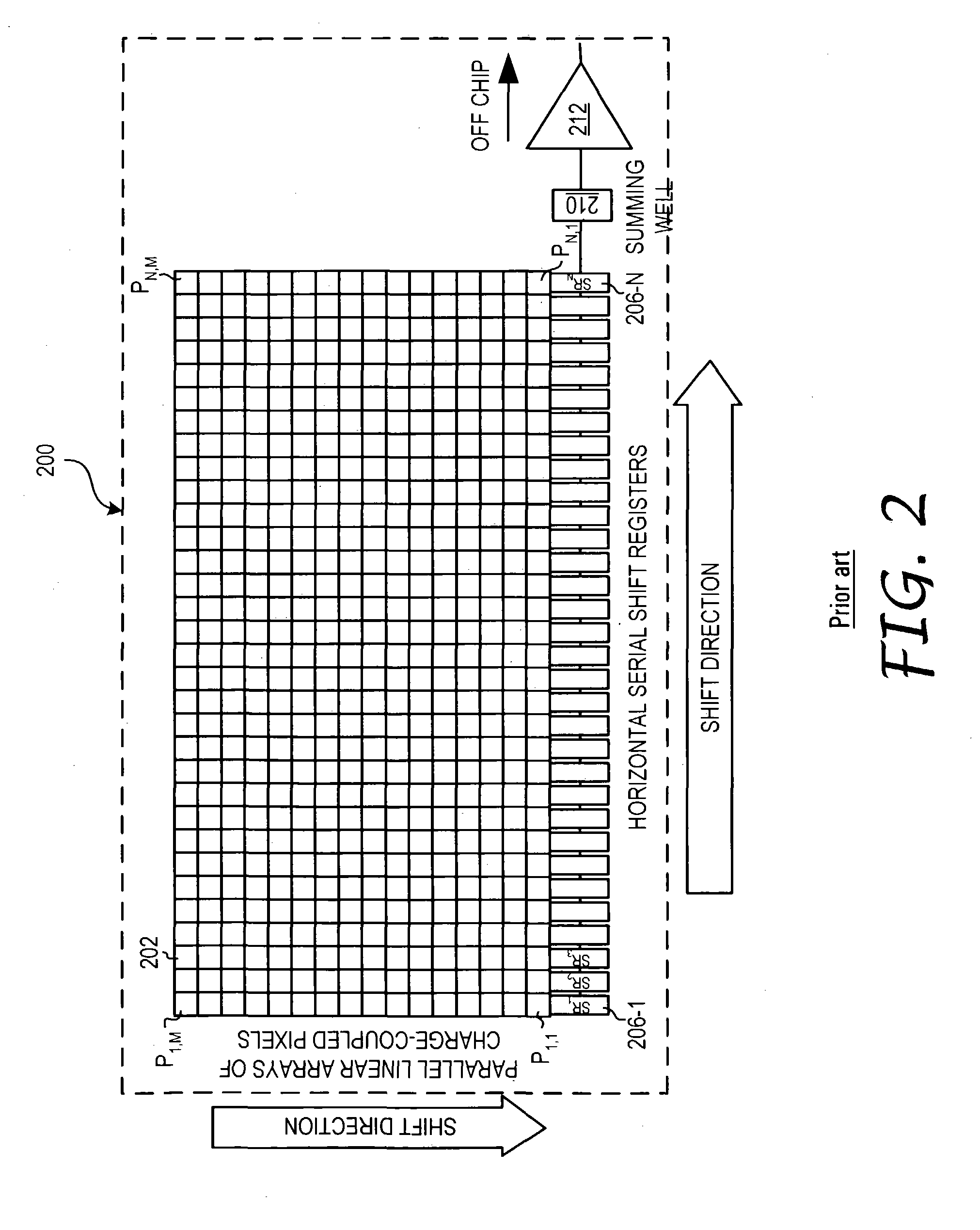
The presently described invention is applicable to spectrographs using a CCD with a two-dimensional array of pixels, wherein each parallel line pixels terminate in a shift register. The pixel lines may be oriented in one of the vertical (column) or horizontal (row) direction, but conventionally as a column in the vertical direction. Additionally, the present invention applicable for CCDs in which the full well capacity of the individual horizontal shift register is le...


PUM


Abstract

The present invention is directed to an apparatus, method and software product for enhancing the dynamic range of a CCD sensor without substantially increasing the noise. Initially, the area of a N×M pixel CCD sensor array is subdivided into two regions, a large region having (M−a) pixels in each column for outputting large-amplitude signals with low noise and a smaller region having a pixels in each column for outputting small-amplitude signals with improved dynamic range. At integration time, the CCD is read out one region's rows at a time into the horizontal shift registers by shifting the pixel charges in either a or M−a vertical shifts. The charges in the horizontal shift registers are then shifted out of the horizontal shift registers in N horizontal shifts. Next, the remaining pixels in the region of the CCD are read out into the horizontal shift registers by shifting the pixel charges in the other of a or M−a vertical shifts. Those charges are then shifted out of the horizontal shift registers in N horizontal shifts. In a spectrographic application, the data from the two regions is read out in the form of a large-amplitude channel from the larger region's rows and a small-amplitude channel from the smaller region's rows.

Description

BACKGROUND OF THE INVENTION 1. Field of the Invention The present invention relates to optical imaging. More particularly, the present invention relates to reading out spectral data from an optical sensor. Still more particularly, the present invention relates to an apparatus, method and software program product for enhancing the dynamic range of spectral data read from an imaging sensor. 2. Description of Related Art The present invention relates to optical spectroscopy measurement instruments which employ an array of sensors in the focal plane to provide substantially simultaneous measurement of light intensity at multiple wavelengths over a broad wavelength range. The advantage of being able to monitor many wavelengths at once has led to the proliferation of these instruments, known collectively as spectrographs. Prior to the development of solid state sensor arrays, the spectroscopy instrument of choice was the monochromator. In a monochromator, a single narrow wavelength re...

Claims


Application Information

Patent Timeline
IPC IPC(8): H04N5/347H04N5/355
CPCG01J3/2803H04N3/1525H04N5/3728H04N5/347H04N5/35563H04N3/155H04N25/46H04N25/57H04N25/73H04N25/713G01J3/457H04N3/1562H04N25/585
Inventor KUENY, ANDREW WEEKS
Owner VERITY INSTR
Why Eureka
Try Eureka