Non-contact optical polarization angle encoder

a technology of rotation encoding and encoder, which is applied in the direction of optical radiation measurement, instruments, photoelectric discharge tubes, etc., can solve the problems of high cost, limited function of code wheels, and inability to withstand environmental extremes, and achieves greater tolerance to environmental extremes and higher frequency

Inactive Publication Date: 2005-01-06
VISIDYNE
View PDF22 Cites 27 Cited by
  • Summary
  • Abstract
  • Description
  • Claims
  • Application Information

AI Technical Summary

Benefits of technology

It is therefore an object of this invention to provide a non-contact optical system and method of measuring and encoding the angl...

Problems solved by technology

The manufacturing of code wheels requires stamping or lithographic etching, which are both expensive processes.
Furthermore, the function of the code wheel is limited to optical diffraction.
Magnetic encoders are susceptible to interference when used in high-speed systems, such as turbines.
Also, magnetic encoders of the two phase (resolver) or the three phase (synchro) transmitter design, are expensive, have a limited maximum RPM and require an AC power source that further increases their cost.
Hall effect sensors provide relatively low signal levels and have temperature limitations, making them vulnerable to e...

Method used


Image

  • Non-contact optical polarization angle encoder
  • Non-contact optical polarization angle encoder
  • Non-contact optical polarization angle encoder

Examples


Embodiment Construction

Aside from the preferred embodiment or the embodiments disclosed below, this invention is capable of other embodiments and of being practiced or being carried out in various ways. Thus, it is to be understood that the invention is not limited in its application to the details of construction and the arrangements of the components set forth in the following description of the invention or illustrated in the drawings in accordance with the invention.

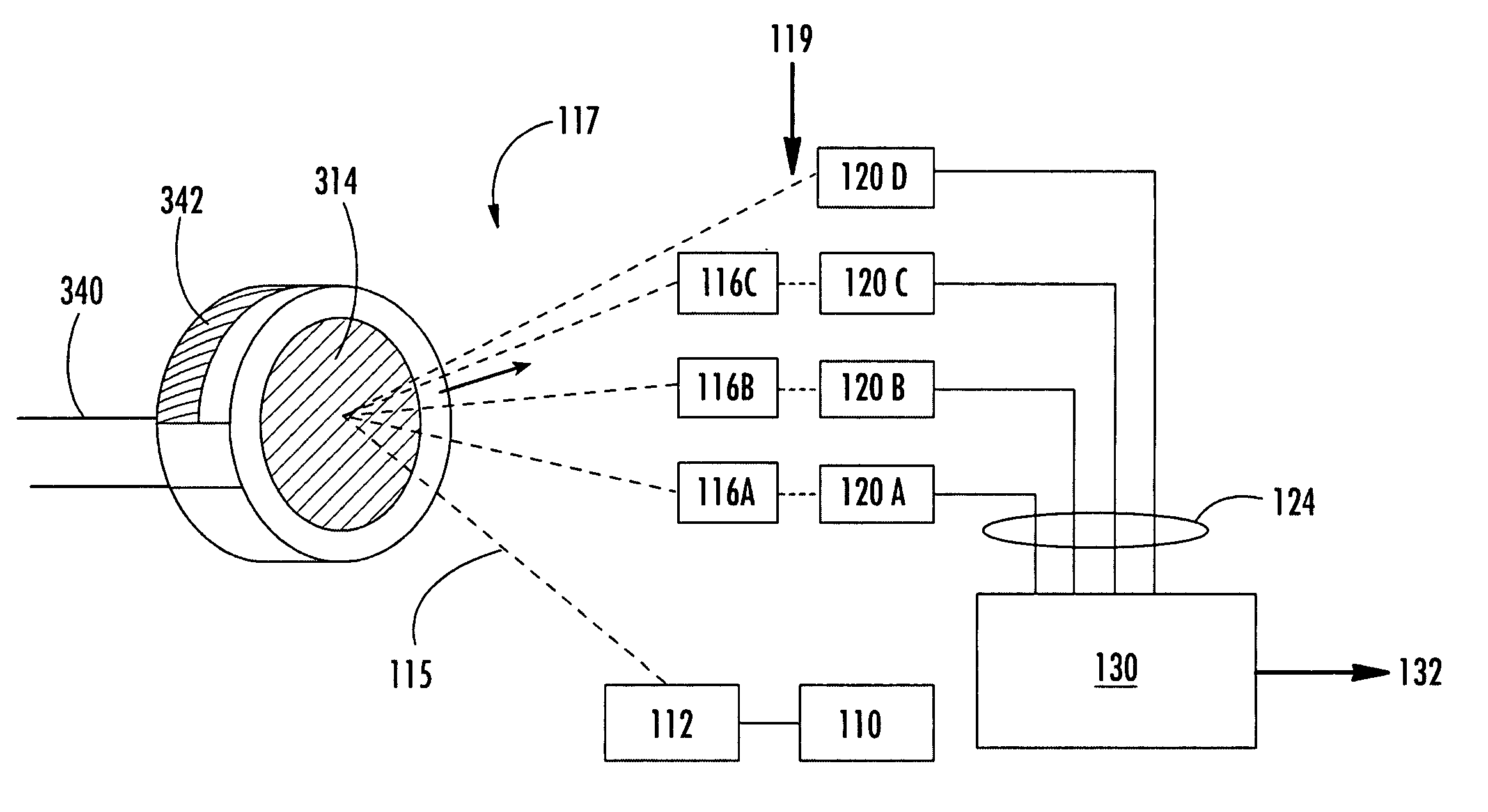
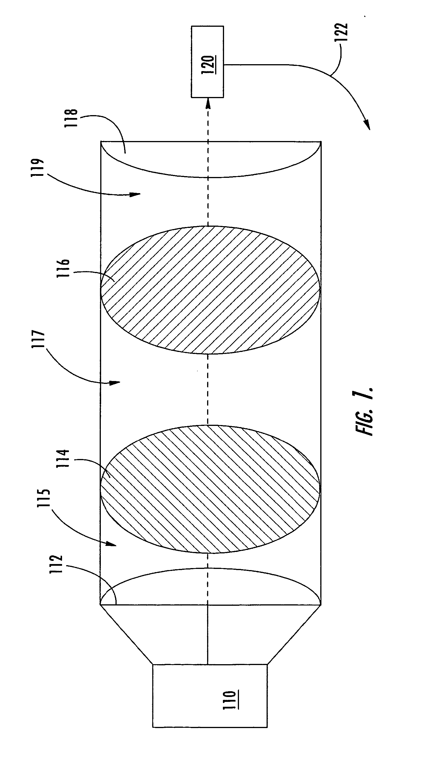
FIG. 1 is a simplified block diagram illustrating the basic principals of encoding an angle of rotation of an object, such as a polarizer 114, using an analyzer 116 (fixed polarizer) and a light detector 120. The position of the polarizer 114 may be fixed or rotating. A light source 110 projects light 115 through a lens 112 and towards a rotating polarizer 114. The light 117 passes through the rotating polarizer 114 and towards the analyzer 116. The analyzer 116 is a fixed polarizer. Light 119 passes through the analyzer 116 and through ...


PUM


Abstract

An optically coupled rotary encoder that is capable of measuring and encoding the angle of rotation of a rotating or stationary object. A polarizer rotates synchronously with the rotatable object and inputs broadband or single frequency unpolarized light. The polarizer outputs and directs polarized light towards a plurality of fixed analyzers and light detectors. Each fixed analyzer outputs and directs further polarized light towards one of the light detectors. Each light detector outputs an electrical signal to a phase processor based upon one attribute of the further polarized light. The phase processor outputs a phase angle with high resolution (>12 bit) with high accuracy and frequency (5 MHz). The system and method can operate in harsh environments having high temperatures, dirt and debris and is not susceptible to EMI/RFI.

Description

FIELD OF THE INVENTION This invention relates to a non-contact optical angle of rotation encoding system and method and more particularly to a system which enables measurement of the angle of rotation of a rotating or fixed object. BACKGROUND OF THE INVENTION Most prior art angle of rotation encoders involve the use of code wheels, magnetic encoders or hall effect sensors. The manufacturing of code wheels requires stamping or lithographic etching, which are both expensive processes. Furthermore, the function of the code wheel is limited to optical diffraction. This constrains the size of code wheels to larger devices. Magnetic encoders are susceptible to interference when used in high-speed systems, such as turbines. Also, magnetic encoders of the two phase (resolver) or the three phase (synchro) transmitter design, are expensive, have a limited maximum RPM and require an AC power source that further increases their cost. Hall effect sensors provide relatively low signal levels a...

Claims


Application Information

Patent Timeline
IPC IPC(8): G01D5/34G01D5/347
CPCG01D5/344G01D5/3473G01D5/34715G01D5/345
Inventor WIJNTJES, GEERT JOHANNESMARKOS, CONSTANTINE T.
Owner VISIDYNE
Why Eureka
Try Eureka