Vector-controlled dual inverter system and method for induction motor

a dual-inverter, inverter technology, applied in the direction of electric generator control, dynamo-electric converter control, dynamo-electric gear control, etc., can solve the problems of deterioration of regeneration power, difficult control of isa and torque of induction motor, and increase of energy loss during power transfer, so as to prevent a decrease of output power

Inactive Publication Date: 2005-01-06
HYUNDAI MOTOR CO LTD +1
View PDF3 Cites 41 Cited by
  • Summary
  • Abstract
  • Description
  • Claims
  • Application Information

AI Technical Summary

Benefits of technology

The deficiencies of conventional systems and methods are overcome by a dual inverter system including two inverter systems. A first inverter system is configured to compensate reactive power to prevent a decrease of output power, and a second inverter system is configured to compensate back EMF to prevent a decrease of output power.

Problems solved by technology

If the back EMF exceeds the maximum voltage that can be supplied from a D.C. power source such as a battery, it becomes difficult to control the angular velocity of the ISA and the torque of the induction motor.
When the back EMF constant is decreased, however, the torque constant is also decreased resulting in the deterioration of regeneration power.
A reduction gear can be adapted to compensate the decreased output torque of the induction motor, but when the reduction gear is adapted, energy loss during power transfer increases such that the overall energy efficiency of the system decreases.

Method used


Image

  • Vector-controlled dual inverter system and method for induction motor
  • Vector-controlled dual inverter system and method for induction motor
  • Vector-controlled dual inverter system and method for induction motor

Examples


Embodiment Construction

Overview of Dual Inverter System

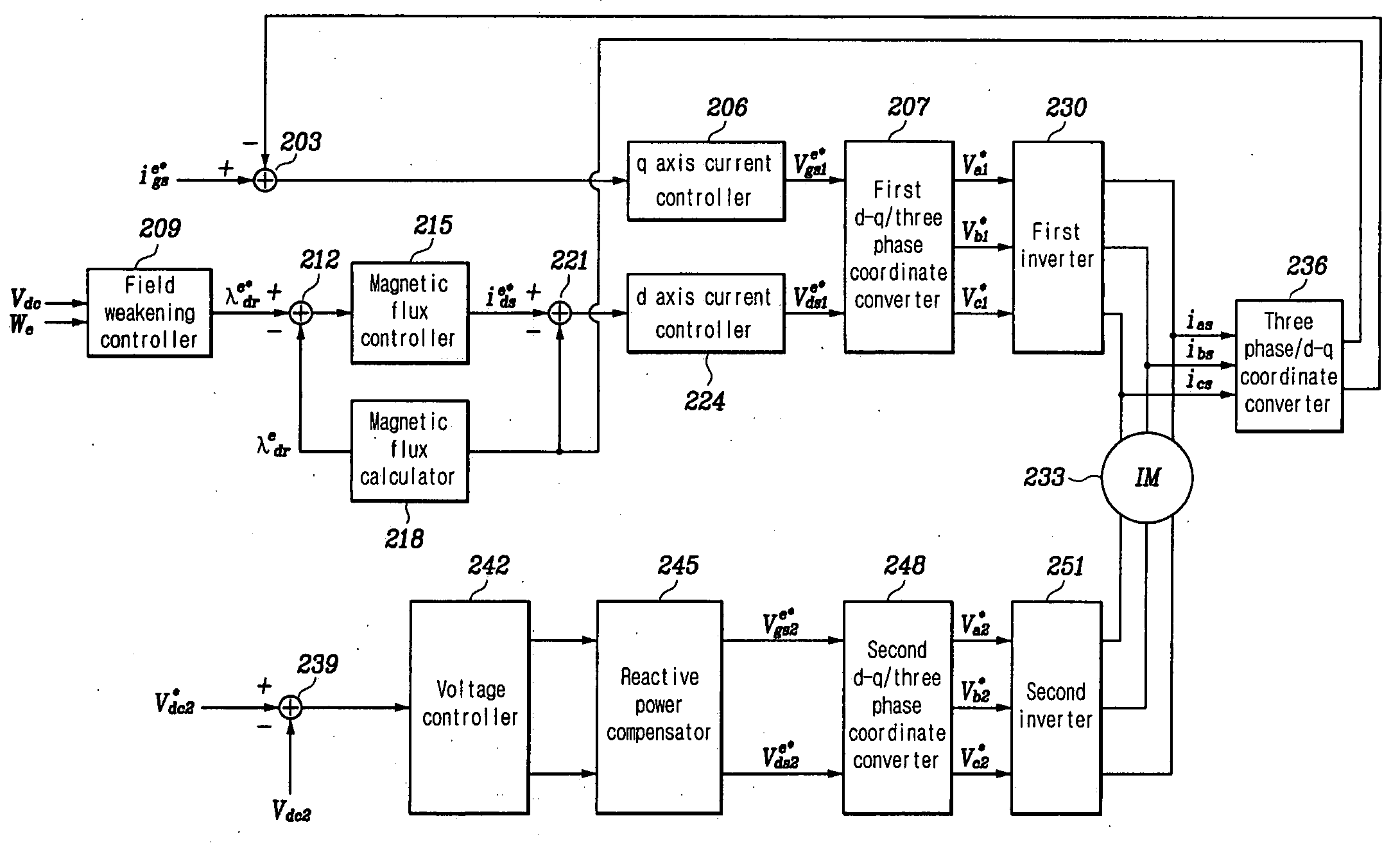
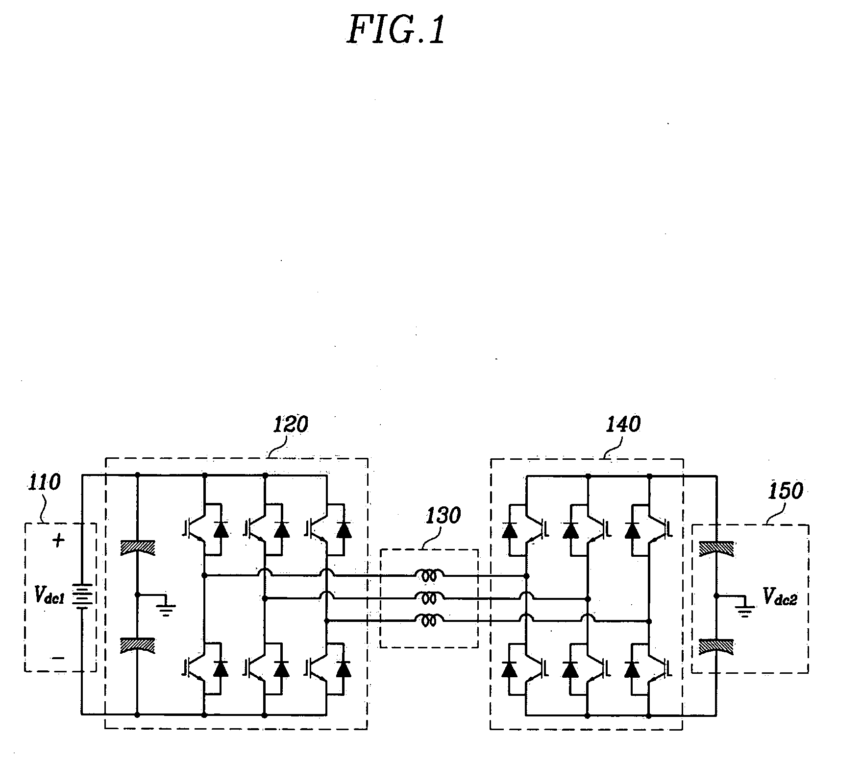
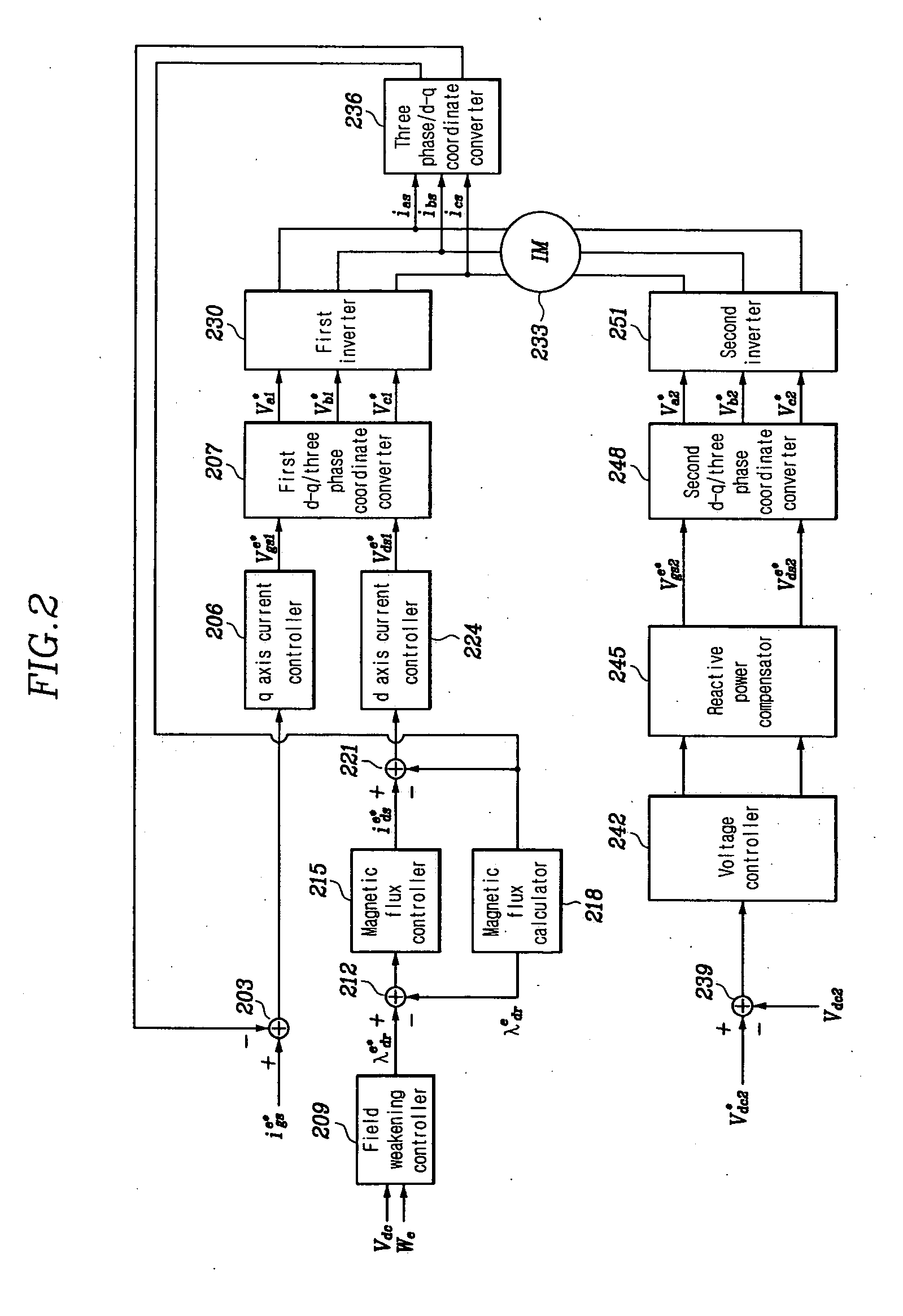
FIG. 1 is a block diagram of a dual inverter system according to an embodiment of this invention. The dual inter system includes a first inverter system 120 and a second inverter system 140. A three phase induction motor 130 is provided such that one end of the induction motor's stator windings are connected to the first inverter system 120, and the other end of the stator windings are connected to the second inverter system 140. A D.C. power source 110 (e.g., a battery) is connected to the first inverter system 120 and supplies D.C. power (Vdc1) to the inverter system 120. The first inverter system 120 converts the D.C. power from the power source 110 into three-phase A.C. power, and performs back EMF compensation to supply the three phase induction motor 130 with the three-phase A.C. power.

A capacitor 150 is connected to the second inverter system 140 to supply D.C. power (Vdc2) to the second inverter system 140. The second inverter system 140 c...


PUM


Abstract

A vector-controlled, dual inverter system for a three-phase induction motor is disclosed. The inverter system comprises a first inverter system which is connected to one end of three phase windings of a stator and performs compensation of a back electromotive force; and a second inverter system which is connected to the other end of the three windings of the stator and performs reactive power compensation.

Description

CROSS-REFERENCE TO RELATED APPLICATIONS This application claims priority of Korean Application No. 10-2003-0045215, filed on Jul. 4, 2003, the disclosure of which is incorporated fully herein by reference. FIELD OF THE INVENTION The disclosed embodiments relate generally to a power inverter system, and more particularly to a power inverter system for controlling speed and torque of an induction motor utilizing a vector-controlled dual inverter. BACKGROUND HEVs (Hybrid Electric Vehicles) typically include an ISA (Integrated Starter and Alternator), which is an apparatus that functions as a starter, alternator, and torque assister. When the ISA is provided as an induction motor the amount of back electromotive force (back EMF) and reactive power generated by the ISA is relatively small, provided its angular velocity is low. As the angular velocity of the ISA increases, however, the amount of back EMF and reactive power also increases. If the back EMF exceeds the maximum voltage tha...

Claims


Application Information

Patent Timeline
Patent Type & Authority Applications(United States)
IPC IPC(8): B60L50/16B60L9/18H02M5/45H02P21/00H02P21/22H02P23/07H02P23/26H02P27/04H02P27/06H02P27/08
CPCB60L11/14B60L15/025B60L2220/12H02M7/5387Y02T10/70H02M2007/53876Y02T10/643Y02T10/7077H02M2001/007B60L50/16H02M1/007H02M7/53876Y02T10/64Y02T10/7072H02P21/00H02P27/06
Inventor MOON, SANG HYUNNAM, KWANG HEEKIM, JUN HA
Owner HYUNDAI MOTOR CO LTD
Why Eureka
Try Eureka