Electronic apparatus and charging method thereof

a technology of electronic equipment and charging method, which is applied in the direction of electric vehicles, secondary cell servicing/maintenance, transportation and packaging, etc., can solve the problems of reducing the output power of the power supplier, consuming power in the charging circuit, and generating heat, so as to reduce the power consumption caused by charging the battery module of the electronic apparatus

Active Publication Date: 2019-02-21
COMPAL ELECTRONICS INC
View PDF0 Cites 7 Cited by
  • Summary
  • Abstract
  • Description
  • Claims
  • Application Information

AI Technical Summary

Benefits of technology

[0005]The invention is directed to an electronic apparatus and a charging method thereof, in which a power consumption caused by charging a battery module of the electronic apparatus may be lowered, and the issue that the requirements for charging the battery module and supplying power to the electronic apparatus may not be simultaneously met due to the limitation to an output power of a power supplier may be avoided.

Problems solved by technology

However, when the power conversion is performed, the charging circuit consumes power and thus generates heat, which is especially evident on a light and compact electronic apparatus.
Besides, when an external power supplier charges the battery in the electronic apparatus and provides power to a system load in the electronic apparatus, the output voltage provided by the power supplier is usually limited to a constant voltage specification value of the battery.
In this case, although the overly high terminal voltage of the battery may be avoided, the output power of the power supplier is limited too.
Once the system load in the electronic apparatus has a greater power demand due to the operation, the output power of the power supplier may be insufficient to simultaneously meet the requirements of charging the battery and supplying power to the system load.
As such, the battery needs to be converted from the charging mode to the discharging mode to support the power demand of the system load; thereby, the battery cannot be effectively charged, and the electric quantity of the battery is reduced.

Method used


Image

  • Electronic apparatus and charging method thereof
  • Electronic apparatus and charging method thereof
  • Electronic apparatus and charging method thereof

Examples


Embodiment Construction

[0016]Reference will now be made in detail to the present embodiments of the invention, examples of which are illustrated in the accompanying drawings. Wherever possible, the same reference numbers are used in the drawings and the description to refer to the same or like parts.

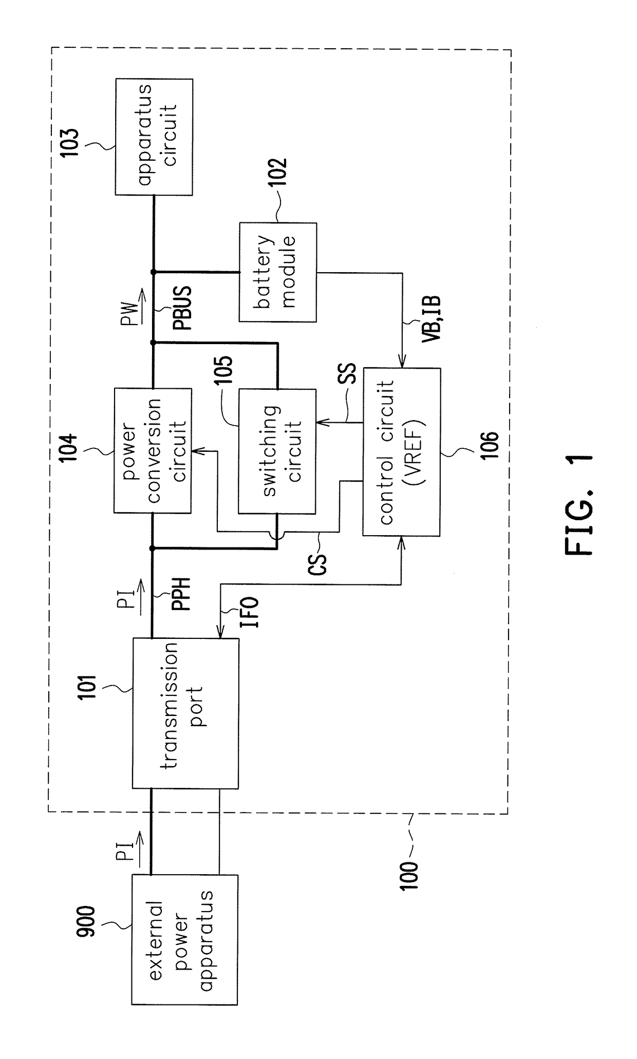
[0017]Hereinafter, referring to FIG. 1, which is a schematic block view of an electronic apparatus illustrated according to an embodiment of the invention. An electronic apparatus 100 may include a transmission port 101, a battery module 102, an apparatus circuit 103, a power conversion circuit 104, a switching circuit 105, and a control circuit 106, but the invention is not limited thereto. The transmission port 101 is configured to be coupled to an external power apparatus 900 to receive an input power PI. The apparatus circuit 103 is connected to the battery module 102 in parallel and coupled to a power bus PBUS. The power conversion circuit 104 is coupled between the transmission port 101 and the power bus...


PUM


Abstract

An electronic apparatus and a charging method thereof are provided. The electronic apparatus includes a transmission port, a battery module, an apparatus circuit, a power conversion circuit, a switching circuit, and a control circuit. The transmission port is coupled to an external power apparatus to receive an input power. The apparatus circuit and the battery module are connected to each other in parallel and are coupled to a power bus. Each of the power conversion circuit and the switching circuit is coupled between the transmission port and the power bus. When the external power apparatus is a programmable power supplier and a battery voltage is lower than a reference voltage, the control circuit disables the power conversion circuit, enables the switching circuit to transmit the input power to the power bus, and regulates a voltage value and a current value of the input power dynamically.

Description

CROSS-REFERENCE TO RELATED APPLICATION[0001]This application claims the priority benefit of Taiwan application serial no. 106128316, filed on Aug. 21, 2017. The entirety of the above-mentioned patent application is hereby incorporated by reference herein and made a part of this specification.BACKGROUND OF THE INVENTION1. Field of the Invention[0002]The invention is related to a charging method, and particularly related to a charging method that may regulate a charging current and a charging voltage dynamically and an electronic apparatus using the charging method.2. Description of Related Art[0003]Nowadays, there are two common methods of supplying power to an electronic apparatus. In one way the power is provided by a battery of the electronic apparatus, and in the other way an external power supplier serves to provide the power to the electronic apparatus or charge the battery inside the electronic apparatus. When the external power supplier provides the power to the electronic ap...

Claims


Application Information

Patent Timeline
Patent Type & Authority Applications(United States)
IPC IPC(8): H02J7/00
CPCH02J7/0081H01M10/44H02J7/0068H02J7/007H02J7/34Y02E60/10H02J7/007184
Inventor LU, SHIH-CHIN
Owner COMPAL ELECTRONICS INC
Why Eureka
Try Eureka