Semiconductor memory device and portable electronic apparatus
- Summary
- Abstract
- Description
- Claims
- Application Information
AI Technical Summary
Benefits of technology
Problems solved by technology
Method used
Image

Examples
Example
[0087] First Embodiment
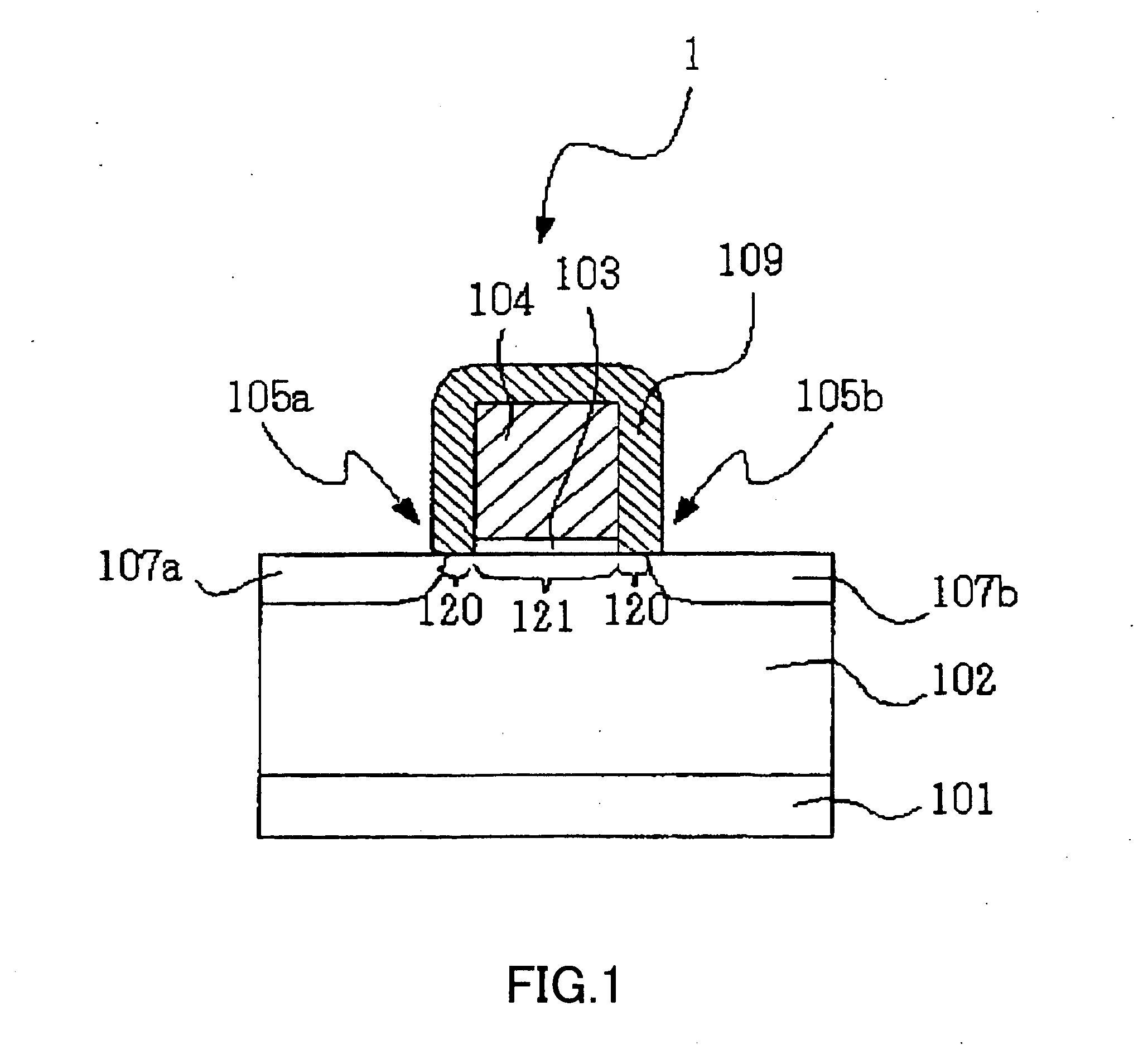
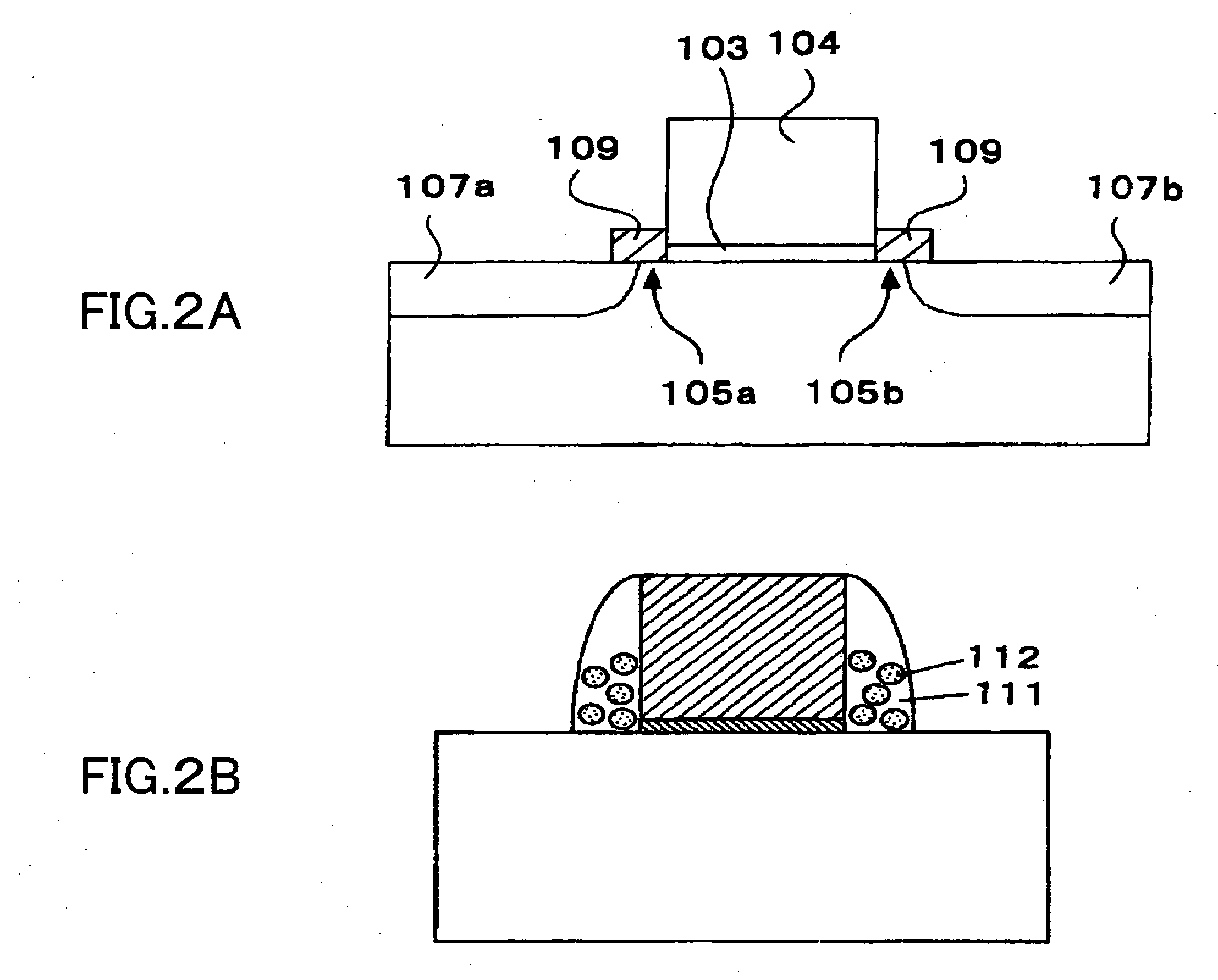
[0088] A semiconductor memory device of a first embodiment has a memory cell 1 as shown in FIG. 1.
[0089] The memory cell 1 has a gate electrode 104 formed on a P-type well region 102 formed on the surface of a semiconductor substrate 101 via a gate insulating film 103. On the top face and side faces of the gate electrode 104, a silicon nitride film 109 having a trap level of retaining charges and serving as a charge retaining film is disposed. In the silicon nitride film 109, parts of both sidewalls of the gate electrode 104 serve as memory functional elements 105a and 105b for actually retaining charges. The memory functional element refers to a part in which charges are actually accumulated by rewriting operation in the memory functional element or the charge retaining film. In the P-type well region 102 on both sides of the gate electrode 104, N-type diffusion regions 107a and 107b functioning as a source region and a drain region, respectively, are forme...
Example
[0109] Second Embodiment
[0110] A memory cell in a semiconductor memory device according to a second embodiment has a configuration substantially similar to that of the memory cell 1 of FIG. 1 except that, as shown in FIG. 8, each of memory functional elements 261 and 262 is configured by a charge retaining region (which is a charge accumulating region and may be a film having the function of retaining charges) and a region for suppressing escape of charges (or a film having the function of suppressing escape of charges).
[0111] Preferably, from the viewpoint of improving the retaining characteristic of the memory, the memory functional element includes a charge retaining film having the function of retaining charges and an insulating film. In the embodiment, a silicon nitride film 242 having a level of trapping charges is used as the charge retaining film and silicon oxide films 241 and 243 having the function of preventing escape of charges accumulated in the charge retaining film...
Example
[0130] Third Embodiment
[0131] The memory functional element 262 in a semiconductor memory device of a third embodiment has a shape in which, as shown in FIG. 13, the silicon nitride film 242 as the charge retaining film has an almost constant thickness and is disposed almost parallel with the surface of the gate insulating film 214 (region 281) and, further, disposed almost parallel with a side surface of the gate electrode 217 (region 282).
[0132] In the case where a positive voltage is applied to the gate electrode 217, an electric line 283 of force in the memory functional element 262 passes through the silicon nitride film 242 twice (portions corresponding to the regions 282 and 281) as shown by the arrows. When a negative voltage is applied to the gate electrode 217, the direction of the electric line of force is reversed. The dielectric constant of the silicon nitride film 242 is about 6 and the dielectric constant of the silicon oxide films 241 and 243 is about 4. Therefore,...
PUM
 Abstract
Description
Claims
Application Information
 - R&D
- Intellectual Property
- Life Sciences
- Materials
- Tech Scout
- Unparalleled Data Quality
- Higher Quality Content
- 60% Fewer Hallucinations
Browse by: Latest US Patents, China's latest patents, Technical Efficacy Thesaurus, Application Domain, Technology Topic, Popular Technical Reports.
© 2025 PatSnap. All rights reserved.Legal|Privacy policy|Modern Slavery Act Transparency Statement|Sitemap|About US| Contact US: help@patsnap.com