Optical system, lens module and electronic equipment
An optical system and lens technology, applied in optics, optical components, instruments, etc., can solve problems such as affecting the thickness of mobile devices
- Summary
- Abstract
- Description
- Claims
- Application Information
AI Technical Summary
Problems solved by technology
Method used
Image

Examples
no. 1 example
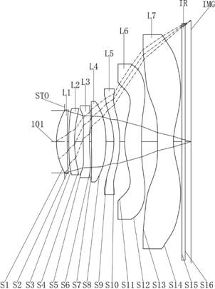
Please refer to figure 1 and figure 2 , the optical system of this embodiment, from the object side to the image side sequentially includes:
The first lens L1 has a positive bending force, the object side S1 of the first lens L1 is convex at the near optical axis 101 , and the image side S2 is concave at the near optical axis 101 .
[0044] The second lens L2 has a negative bending force. The object side S3 of the second lens L2 is convex at the near optical axis 101 , and the image side S4 is concave at the near optical axis 101 .
[0045] The third lens L3 has a negative bending force. The object side S5 of the third lens L3 is convex at the near optical axis 101 , and the image side S6 is concave at the near optical axis 101 .
[0046] The fourth lens L4 has a positive bending force, the object side S7 of the fourth lens L4 is convex at the near optical axis 101 , and the image side S8 is convex at the near optical axis 101 .
[0047] The fifth lens L5 has a...
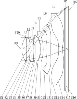
no. 2 example
[0059] The second lens L2 has a negative bending force. The object side S3 of the second lens L2 is convex at the near optical axis 101 , and the image side S4 is concave at the near optical axis 101 .
[0060] The third lens L3 has a positive bending force, the object side S5 of the third lens L3 is convex at the near optical axis 101 , and the image side S6 is concave at the near optical axis 101 .
[0061] The fourth lens L4 has a positive bending force, the object side S7 of the fourth lens L4 is concave at the near optical axis 101 , and the image side S8 is convex at the near optical axis 101 .
[0062] The fifth lens L5 has a negative bending force. The object side S9 of the fifth lens L5 is concave at the near optical axis 101 , and the image side S10 is convex at the near optical axis 101 .
[0063] The sixth lens L6 has a positive bending force, the object side S11 of the sixth lens L6 is convex at the near optical axis 101 , and the image side S12 is conca...
no. 3 example
[0070] The second lens L2 has a negative bending force. The object side S3 of the second lens L2 is convex at the near optical axis 101 , and the image side S4 is concave at the near optical axis 101 .
[0071] The third lens L3 has a negative bending force. The object side S5 of the third lens L3 is convex at the near optical axis 101 , and the image side S6 is concave at the near optical axis 101 .
[0072] The fourth lens L4 has a positive bending force, the object side S7 of the fourth lens L4 is concave at the near optical axis 101 , and the image side S8 is convex at the near optical axis 101 .
[0073] The fifth lens L5 has a negative bending force. The object side S9 of the fifth lens L5 is concave at the near optical axis 101 , and the image side S10 is convex at the near optical axis 101 .
[0074] The sixth lens L6 has a positive bending force, the object side S11 of the sixth lens L6 is convex at the near optical axis 101 , and the image side S12 is concav...
PUM
 Abstract
Description
Claims
Application Information
 - R&D
- Intellectual Property
- Life Sciences
- Materials
- Tech Scout
- Unparalleled Data Quality
- Higher Quality Content
- 60% Fewer Hallucinations
Browse by: Latest US Patents, China's latest patents, Technical Efficacy Thesaurus, Application Domain, Technology Topic, Popular Technical Reports.
© 2025 PatSnap. All rights reserved.Legal|Privacy policy|Modern Slavery Act Transparency Statement|Sitemap|About US| Contact US: help@patsnap.com