Micro-structure light guide plate and display module thereof

A light guide plate and microstructure technology, applied in the field of light guide plates, can solve the problems of thick thickness of the whole machine, uneven grooves, difficult to make appearance effects, etc., and achieve the effect of improving strength, increasing smoothness and diffuse reflectivity

Pending Publication Date: 2018-12-11
苏州本瑞光电科技有限公司
View PDF0 Cites 2 Cited by
  • Summary
  • Abstract
  • Description
  • Claims
  • Application Information

AI Technical Summary

Problems solved by technology

[0004] The structure of the liquid crystal module using the existing light guide plate structure is complicated, the thickness of the whole machine is relatively thick, and the cost is high. Moreover, the backplane is generally made of metal or plastic parts, and its color is single, so it is difficult to produce different appearance effects.
In order to achieve the ultra-thin design of the display module, the thickness of the light guide plate is usually reduced. After the thickness of the light guide plate is reduced, the thickness of the matching LED is also reduced. However, the brightness of the existing ultra-thin LED cannot meet the high brightness of large-size TVs. need
At the same time, after PMMA becomes thinner, it is easy to deform, resulting in uneven light input and local light leakage.
In recent years, Corning has developed ultra-transparent glass, which is comparable to the transmittance and transparency of optical acrylic. Some use traditional techniques to screen-print dots on the back of the glass and use them on monitors and TVs. However, for smaller sizes, the size of the printed dots is low. After 0.2mm, the process is not suitable for mass production, and cannot be applied to small-sized and ultra-thin light guide plates
At present, laser technology is used to prepare grooves. There are micro cracks in the grooves, which cause glass damage. At the same time, the grooves are not uniform, and the optical scattering points formed by the grooves are not soft.

Method used


Image

  • Micro-structure light guide plate and display module thereof
  • Micro-structure light guide plate and display module thereof
  • Micro-structure light guide plate and display module thereof

Examples


Embodiment Construction

[0033] The above solution will be further described below in conjunction with specific embodiments. It should be understood that these examples are used to illustrate the present invention and not to limit the scope of the present invention. The implementation conditions used in the examples can be further adjusted according to the conditions of specific manufacturers, and the implementation conditions not indicated are usually the conditions in routine experiments.

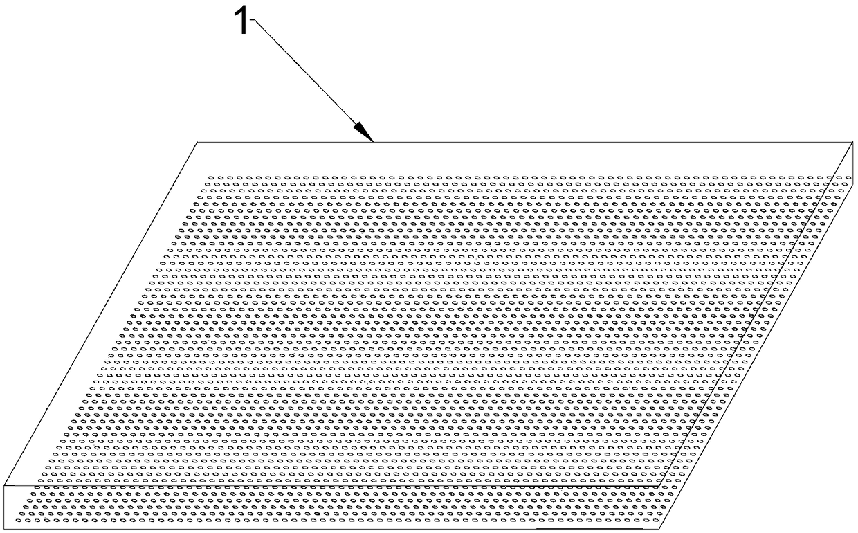
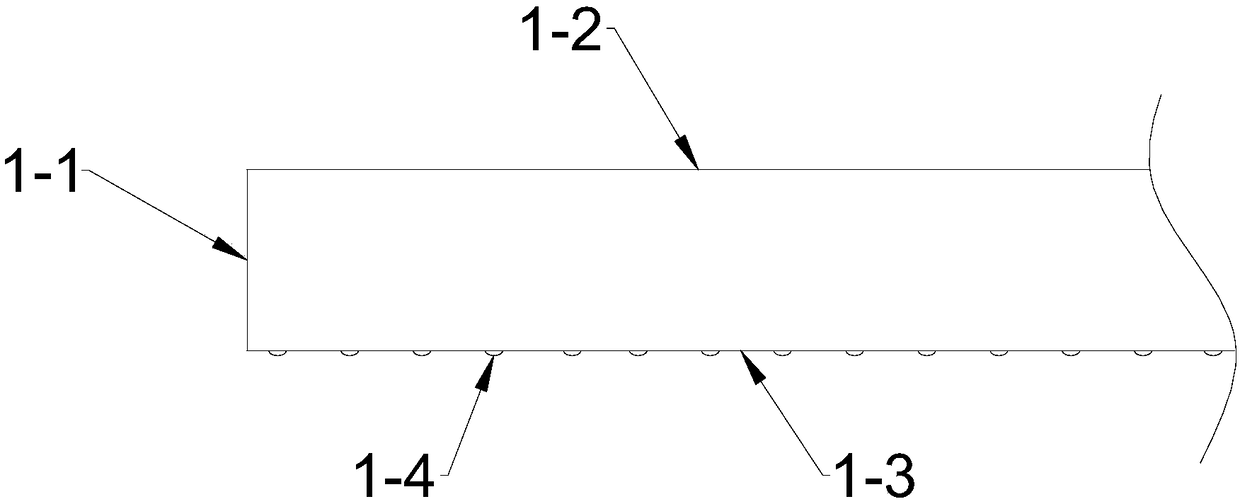
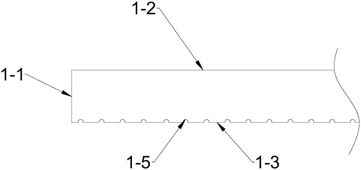
[0034] see Figure 5 , which is a structural schematic diagram of the present invention, provides a microstructured light guide plate, including a light guide plate body 100, the light guide plate body 100 has a light incident surface 101, a light exit surface 102, and a back surface 103, and several micro grooves are arranged on the back surface Structure 104, the improvement of the present invention is that a resin layer 105 is deposited on the back side 103, and the resin layer 105 is one of epoxy resin, phen...


PUM

PropertyMeasurementUnit
refractive indexaaaaaaaaaa

Abstract

The invention discloses a micro-structure light guide plate and a display module thereof. The micro-structure light guide plate comprises a light guide plate body (100), the light guide plate body (100) comprises a light-inlet surface (101), a light-outlet surface (102) and a backside (103), the backside (103) is provided with a plurality of groove micro-structures (104), and a resin layer (105) is deposited on the backside (103). According to the micro-structure light guide plate and the display module thereof, the strength of the light guide plate can be improved, the image quality is uniformized, and the realization of light weight and thinning of the display module is facilitated.

Description

technical field [0001] The invention relates to the technical field of light guide plates, in particular to a microstructure light guide plate and a display module thereof. Background technique [0002] Existing light guide plates generally use optical-grade acrylic materials, which can be prepared by printing, injection, hot pressing, inkjet, etc. The structure of the light guide plate is usually a cuboid, and the light incident surface is perpendicular to the light exit surface, such as figure 1 . figure 2 , 3 1-1 is the light-incoming surface of the light guide plate, 1-2 is the light-emitting surface of the light guide plate, 1-3 is the back side of the light guide plate, 1-4 is the raised microstructure, and 1-5 is the groove microstructure. in figure 2 It is a raised microstructure formed by printing, spray printing, embossing, etc., image 3 For the grooved microstructure formed by hot pressing, laser. The size of the light output can be adjusted according to ...

Claims


Application Information

Patent Timeline
Patent Type & Authority Applications(China)
IPC IPC(8): G02B6/00G02F1/13357
CPCG02B6/0043G02B6/0051G02B6/0055G02F1/133606G02F1/133607G02F1/133614
Inventor 张兴国毛新磊汤存一
Owner 苏州本瑞光电科技有限公司
Why Eureka
Try Eureka