

Stiffness-taper tubing and the manufacturing method, and manufacturing apparatus for such tubing
- Summary
- Abstract
- Description
- Claims
- Application Information
AI Technical Summary
Benefits of technology
Problems solved by technology
Method used
Image

Examples
Embodiment Construction
1. Field of the Invention
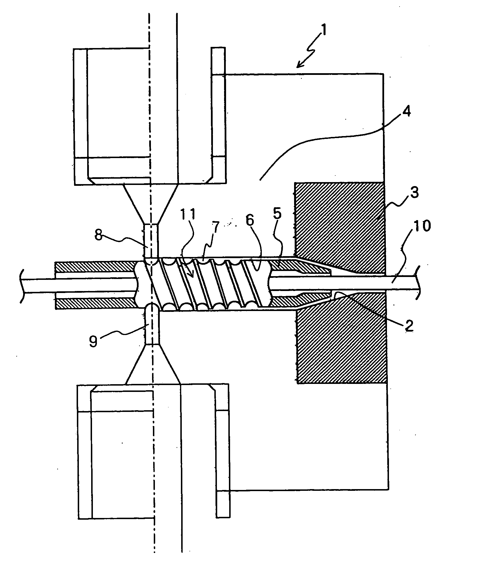
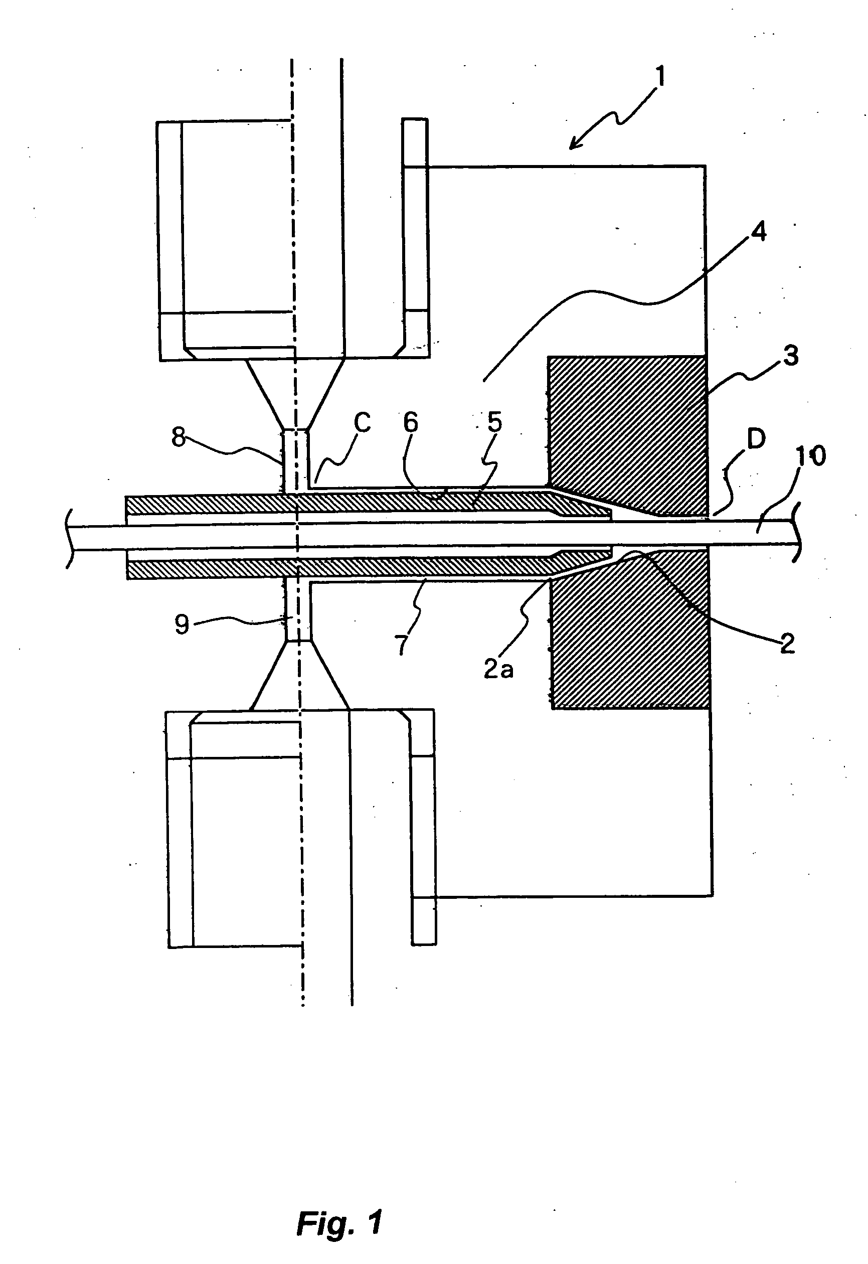
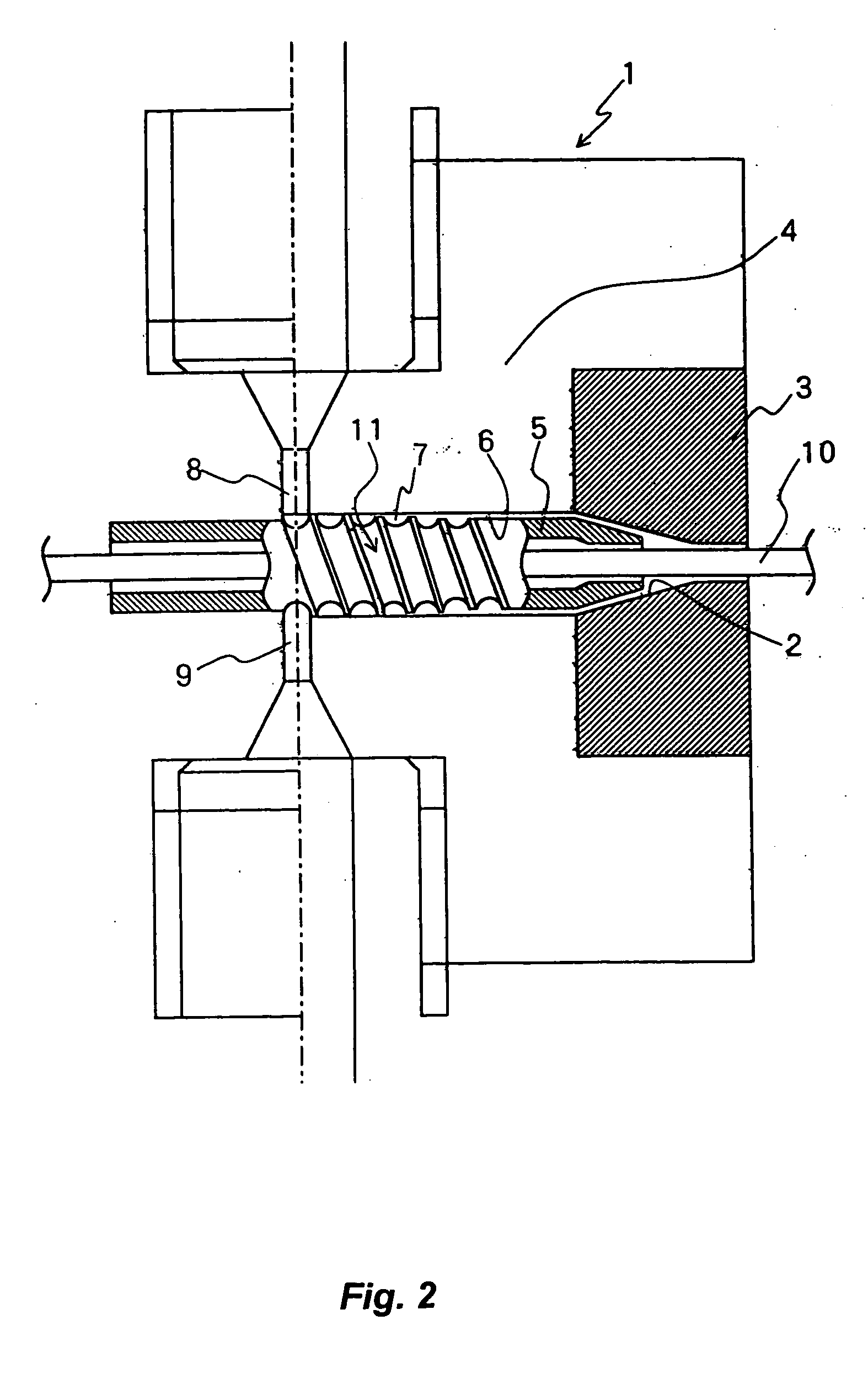
This invention relates to stiffness-taper tubing, that is formed by joining two or more resin materials having different stiffness such that the stiffness along its length gradually changes, and to the manufacturing method and manufacturing apparatus for such tubing. The stiffness-taper tubing of this invention is suitable for use in medical applications such as a catheter.
2. Background of the Invention
Conventionally, a two-layer extrusion-type formation apparatus was used when using two types of resin materials having different stiffness to form stiffness-taper tubing. The stiffness-taper tubing was formed such that there was a stiff section made from a first resin, having much stiffness in the longitudinal direction, a soft section made from a second resin, having little stiffness, and a transition section between these two sections in which the stiffness gradually changed (stiffness taper section). For this kind of stiffness-taper tubing, the first...
PUM
| Property | Measurement | Unit |
|---|---|---|
| Strength | aaaaa | aaaaa |
| Stiffness | aaaaa | aaaaa |
Abstract
Description
Claims
Application Information