Fuel cell system

a fuel cell and system technology, applied in the field of fuel cell systems, can solve the problems of the energy density reduction of the entire fuel cell system, and achieve the effect of reducing the cost of the system and miniaturizing i

Active Publication Date: 2005-01-06
MURATA MFG CO LTD
View PDF3 Cites 11 Cited by
  • Summary
  • Abstract
  • Description
  • Claims
  • Application Information

AI Technical Summary

Benefits of technology

Accordingly, as compared with a case that the number of unit cells or the electrode area is equal to the optimum value nopt, reduction in the cost of the system and miniaturization thereof may be achieved by decreasing the number of unit cells or the electrode area.

Problems solved by technology

Accordingly, the related system has a drawback in that energy density of the entire fuel cell system decreases.

Method used


Image

  • Fuel cell system
  • Fuel cell system
  • Fuel cell system

Examples


example

Next, a practical example is described hereinbelow by referring to results of a simulation, which are illustrated in FIGS. 2A to 5.

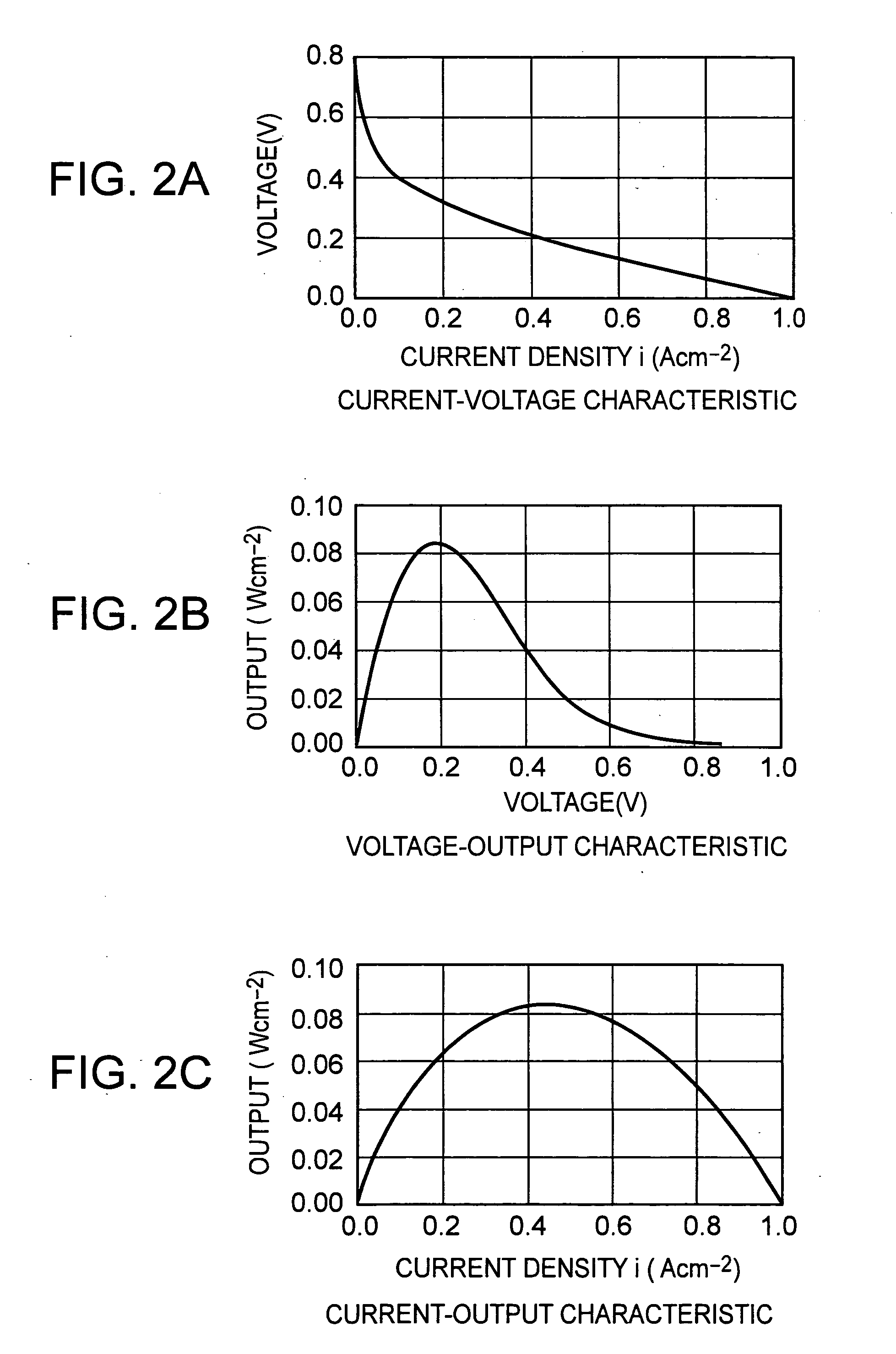
FIGS. 2A, 2B, and 2C illustrate characteristics of each of unit cells used in this example according to an embodiment of the present invention. FIG. 2A is a graph, whose axis of abscissa represents a current density and whose axis of ordinates represents a voltage, for illustrating a current-voltage characteristic. FIG. 2B is a graph, whose axis of abscissa represents a voltage and whose axis of ordinates represents a output density, for illustrating a voltage-output characteristic; and FIG. 2C is a graph, whose axis of abscissa represents a current density and whose axis of ordinates represents an output density, for illustrating a current-output characteristic.

These characteristics were obtained by a simulation. In practice, the unit cell is connected to, for instance, a device that may control the load. The characteristics may be obtained by measu...


PUM

PropertyMeasurementUnit
volumeaaaaaaaaaa
energyaaaaaaaaaa
energy densityaaaaaaaaaa

Abstract

The present invention provides a fuel cell system that has a fuel cell portion including one or more unit cells, a fuel tank for storing fuel used in the unit cells, and a control portion for controlling the fuel cell portion. The number of unit cells is optimized so that a total amount of energy, which is outputted from the fuel cell system as a function of the number of unit cells or of an electrode area, shows a maximum value or a nearly maximum value. Thus, the amount of energy may be maximized or made to be equal to or more than a predetermined value. Accordingly, target devices to be supplied with power from the fuel cell system may be used for a longer time.

Description

CROSS REFERENCES TO RELATED APPLICATIONS The present invention claims priority to its priority document No. 2003-152092 filed in the Japanese Patent Office on May 29, 2003, the entire contents of which being incorporated by reference herein. BACKGROUND OF THE INVENTION 1. Field of the Invention The present invention relates to techniques for optimizing the number of unit cells or the electrode area thereof so as to maximize an amount of energy which the fuel cell system can output, thereby lengthening a drive time of a device to be supplied with electric power from a fuel cell system. 2. Description of Related Art Recent advancement in functionality of portable electronic devices (for example, a notebook personal computer, a video camera, a digital camera, and a portable phone), which is accompanied by expansion of broadband, has a tendency of increase in necessary power for driving the devices. Portable electronic devices are generally battery-operated for convenience thereof...

Claims


Application Information

Patent Timeline
Patent Type & Authority Applications(United States)
IPC IPC(8): H01M8/04H01M8/00H01M8/02H01M8/24
CPCH01M8/02H01M8/04619H01M8/04932Y02B90/18H01M8/249H01M2250/30Y02E60/50H01M8/24Y02B90/10
Inventor UESAKA, SHINICHITOMITA, TAKASHI
Owner MURATA MFG CO LTD
Why Eureka
Try Eureka