Eureka AIR delivers breakthrough ideas for toughest innovation challenges, trusted by R&D personnel around the world.

Method for purging a system for use in administrating therapeutic gas to a patient

a technology for administering therapeutic gas and purging system, which is applied in the field of surgery, can solve the problems of degrading the quality of the high purity gas contained within the remainder, affecting the efficiency of the system, so as to achieve efficient and effective purging system

Inactive Publication Date: 2005-01-06
PULMONOX TECH
View PDF8 Cites 18 Cited by
  • Summary
  • Abstract
  • Description
  • Claims
  • Application Information

AI Technical Summary

Benefits of technology

[0033] It is a main object of the present invention to provide a method for efficiently and effectively purging a system and elements such as disclosed in the incorporated material which deliver NO to a spontaneously breathing, and / or a non-spontaneously breathing and or a mechanically ventilated patient or a non-ventilated patient.
[0035] It is another object of the present invention to provide a method for efficiently and effectively purging a system and elements such as disclosed in the incorporated material which delivers NO to a patient and which has a means for effectively and efficiently equalizing pressure between a source of pressurized gas and the system, but keeping the system pressurized slightly above atmospheric pressure if the gas source is removed.

Problems solved by technology

However, a check valve isolation system may have drawbacks if used in certain circumstances.
When a pressurized gas source is exchanged, there exists the possibility that air will be trapped within the inlet volume of the system plumbing that is exposed to air during the source exchange.
Any trapped air will normally degrade the quality of the high purity gases contained within the remainder of the system when intervening valves are opened.
Surface area plays an important role in gas plumbing quality since contaminants often preferentially adhere to surfaces and can be extremely difficult to remove.
Typically, a flow direction check valve is not able to achieve all of these goals.
However, for purging to be effective, the dead space and other parts of the gas circuit must be substantially swept out and internal surfaces scrubbed by periods of high gas flow.
Purging is often complicated in many situations due to possible toxic effects of the therapeutic gases on bystanders and the high cost of medical grade gases.
If, subsequent to this, a supply is attached that is at a lower pressure than the checked pressure, the system will not be able to detect the connection until the pressure downstream of the check valve has been bled off or not at all.

Method used


Image

  • Method for purging a system for use in administrating therapeutic gas to a patient
  • Method for purging a system for use in administrating therapeutic gas to a patient
  • Method for purging a system for use in administrating therapeutic gas to a patient

Examples


Embodiment Construction

[0063] Other objects, features and advantages of the invention will become apparent from a consideration of the following detailed description and the accompanying drawings.

[0064] Broad System

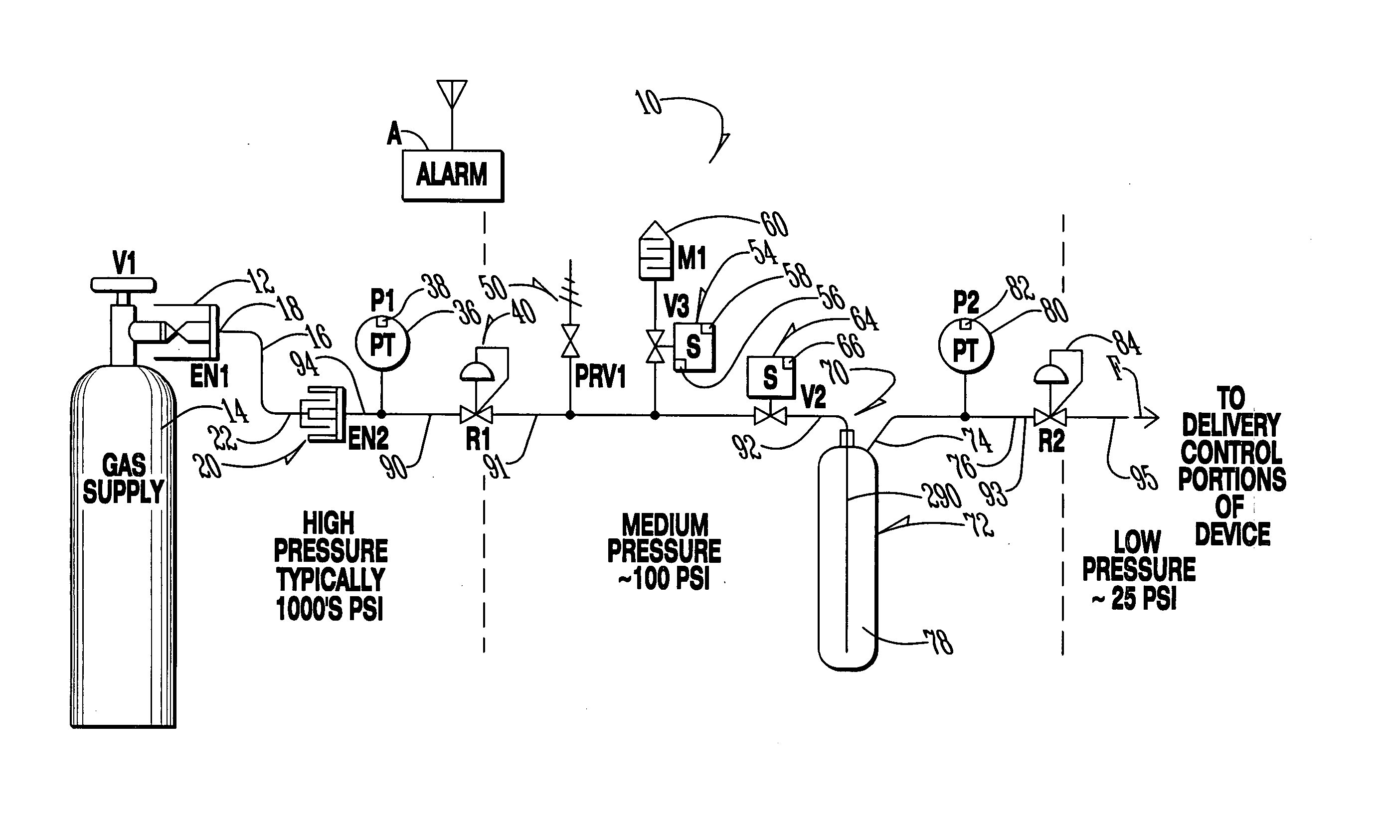
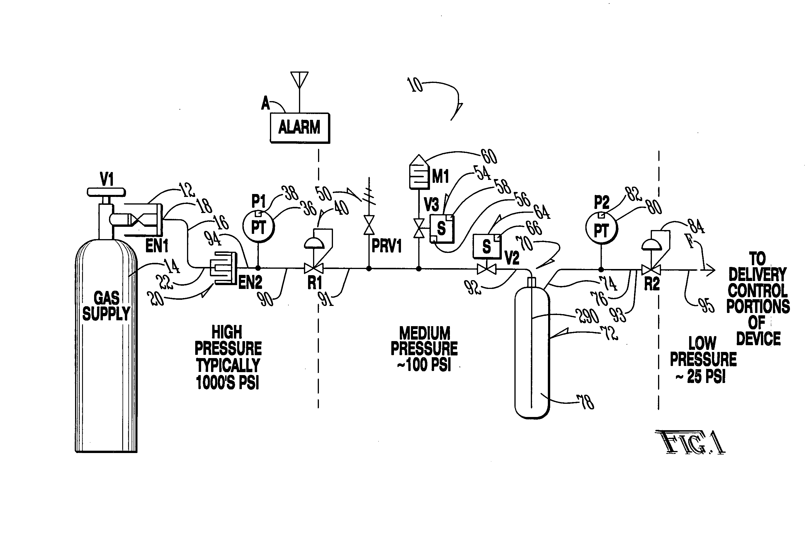
[0065] Referring to FIG. 1, the invention disclosed in the incorporated material is broadly embodied in a system 10 for use in administrating therapeutic gas to a patient. System 10 comprises a first equalization valve 12 that is fluidically connected to a source 14 of therapeutic gas. A first fluid conduit 16 has an inlet end 18 fluidically connected to the first equalization valve to receive fluid from source 14. For purposes of this disclosure, the terms upstream and downstream as well as source side and system side will be with reference to a flow direction from source 14 toward a patient with the flow direction being indicated in FIG. 1 by arrow F. Other terms, such as inlet and outlet will also be with reference to those flow directions.

[0066] As will be discussed below, first equaliza...


PUM


Abstract

A system that controls and manages administration of a therapeutic gas, such as NO, O2, or the like, to a patient is purged using a method that conserves purge gas. The system was fully disclosed in U.S. patent applications Ser. No. 09 / 688,229, filed on Oct. 16, 2000 and Ser. No. 10 / 351,755 filed on Jan. 27, 2003 and includes an equalizing valve and a reservoir.

Description

CROSS REFERENCE TO RELATED APPLICATIONS [0001] The present application is a continuation-in-part of application Ser. No. 10 / 351,755, filed on Jan. 27, 2003 which is a continuation-in-part of application of Ser. No. 09 / 688,229 filed on Oct. 16, 2000, both of which are owned by the assignee of the present application. The present application incorporates herein the disclosures of the 09 / 688,229 and the 10 / 351,755 patent applications by reference.TECHNICAL FIELD OF THE INVENTION [0002] The present invention relates to the general art of surgery, and to the particular field of introducing material to a patient for therapeutic or diagnostic purposes, most specifically, the invention relates to NO therapy. BACKGROUND OF THE INVENTION [0003] As discussed in the referenced and incorporated disclosure, the use of therapeutic gases to treat a human or animal patient has been known in the art for many years. A number of different gases may be added to a respiratory gas that is inhaled by a pat...

Claims


Application Information

Patent Timeline
IPC IPC(8): A61M16/00A61M16/06A61M16/20
CPCA61M16/00A61M16/0816A61M16/208A61M2202/0275A61M16/0677A61M2205/6027A61M2205/8206A61M2205/8237A61M2205/6018A61M2016/0027A61M16/202A61M16/209A61M16/0051A61M16/024
Inventor FIGLEY, CURTISHUNT, DARIN W.
Owner PULMONOX TECH
Why Eureka
Eureka Blog
Learn More