
Pneumoseal trocar arrangement

Active Publication Date: 2005-01-06
IPTECH
View PDF37 Cites 47 Cited by
  • Summary
  • Abstract
  • Description
  • Claims
  • Application Information

AI Technical Summary

Benefits of technology

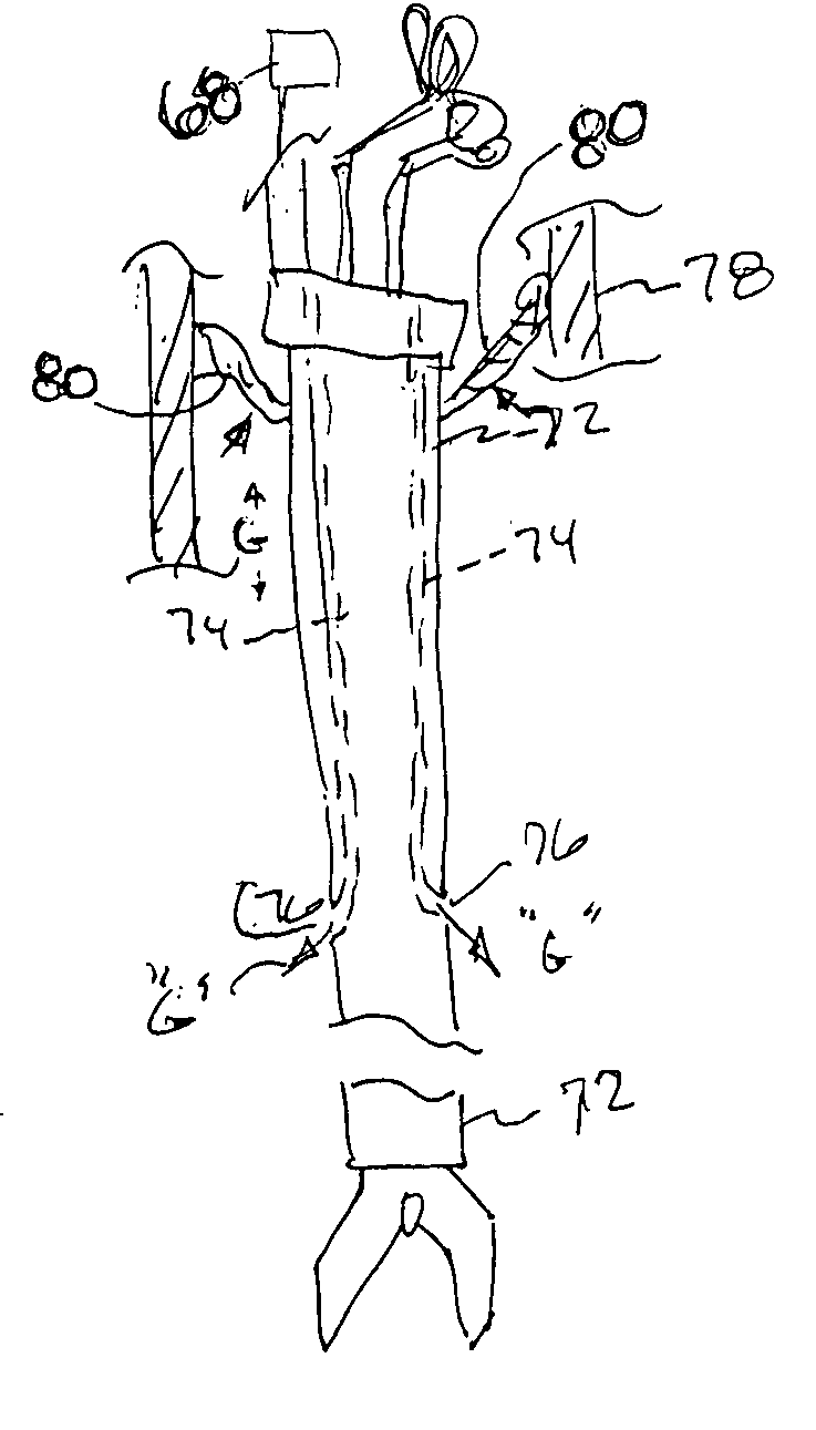
[0011] In a first aspect of the present invention, by positioning a partial obstruction in the outflow path of gas from the pneumoseal of the present invention, the volume of lost gas is reduced by the back pressure. The partial obstruction could be placed anywhere in the cannula, as long as it is proximal to the inflow of gas for the pnuemoseal and the operative pneumoperitoneum. In addition, the active high pressure and high volume of distending gas could be used to increase or decrease the size of the partial obstruction. The partial obstruction of the outflow of gas could be a design feature of only one large bore cannula, several large bore cannulas, or all of the cannulas used in a surgical procedure. Once again, the advantage of a partial obstruction would be to increase the efficiency of a multiple cannula system by decreasing the loss of distension gas from the pneumoseal and the operative pneumoperitoneum. Such partial obstruction of a current dual mechanical valve cannula of the prior art would be surgically inappropriate because it would not be airtight.
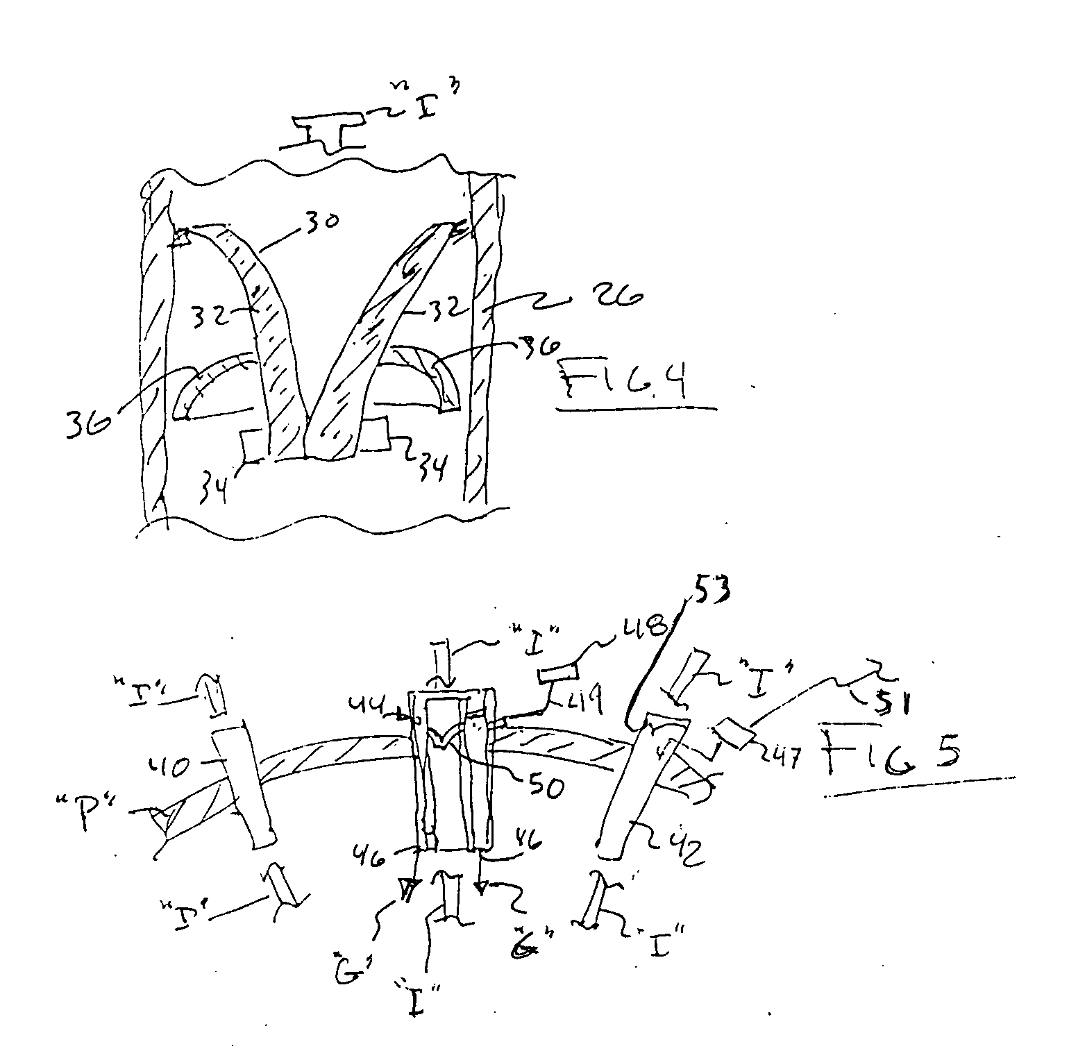
[0012] In a closed pressurized system such as an operative pneumoperitoneum, gas pressure can be measured at any anatomic location. In an open pressurized system, like the pneumoseal system, the pressure maintaining the operative pneumoperitoneum can only be measured within the pneumoperitoneum. This is because in an open pressurized system, the pressure in the inflow, outflow or combined gas streams is only representative of the static peritoneum pressure when measured at some point beyond the distal end of the cannula and within the peritoneum. Outflow of gas through the cannula can be reduced by using a partial obstruction as recited hereinabove. If the outflow of gas were not interrupted by the inflow of gas, the outflow of gas would only be constrained by the flow characteristics of the open cannula and a large flow volume would occur. If the outflowing gas encounters a shaped inflow of high pressure gas within the cannula body, the outflow gas flow characteristics are changed dramatically and the volume of outflowing gas is greatly reduced. This principle is the basis of the pneumoseal cannula. In addition, there would be upward flow gas through the cannula. This upward flow could be used to increase the efficiency of a partial obstruction, increasing the overall efficiency of the “no seal” cannula of the present invention, even when utilizing other components of a multiple cannula system with the patient.
[0013] The present invention, in one aspect increases the efficiency of the pneumoseal cannula by introducing a partial obstruction within the cannula proximal to the air input orifice. Such a cannula of the present invention may be effectively utilized with a plurality of cannulas that are non-obstructed, partially obstructed, or fully obstructed to increase the efficiency of the pneumoseal system of cannulas, which may be measured by the maintenance of an adequately stable operative pneumoperitoneum. A partial obstruction may be made by using an active gas inflow to urge the walls of the partial obstruction to decrease the outflow of gas, by compression on those walls even to the point of creating a total obstruction. Total obstruction created by a series of fins to baffle the air flow and harness lateral closure forces upon the walls of that valve.
[0015] The invention thus comprises a cannula assembly for the maintenance of an operative pneumoperitoneum in a patient comprising an elongated cannula having a proximal end and a distal end. A valve is preferably securely arranged within, on or adjacent the proximal end of the cannula to provide a tight seal and minimize the escape of gas which has been introduced into the patient's pneumoperitoneum when an operative instrument is passed therethrough. The valve may comprise an inner portion of a proximal cap which is fixed or removably attachable to the proximal end of the cannula. The valve assembly may have a compressible O-ring thereon to provide a further seal of the cap to the cannula. The valve may have a plurality of fluid flow directing fins thereon to direct any backflow of gas to tighten the sealing effect of the valve. The valve may have a distal underside with a pocket arrangement thereon to capture any backflowing gas and create a more efficient seal by the valve in the cannula.

Problems solved by technology

Such partial obstruction of a current dual mechanical valve cannula of the prior art would be surgically inappropriate because it would not be airtight.

Method used


Image

  • Pneumoseal trocar arrangement
  • Pneumoseal trocar arrangement
  • Pneumoseal trocar arrangement

Examples


Embodiment Construction

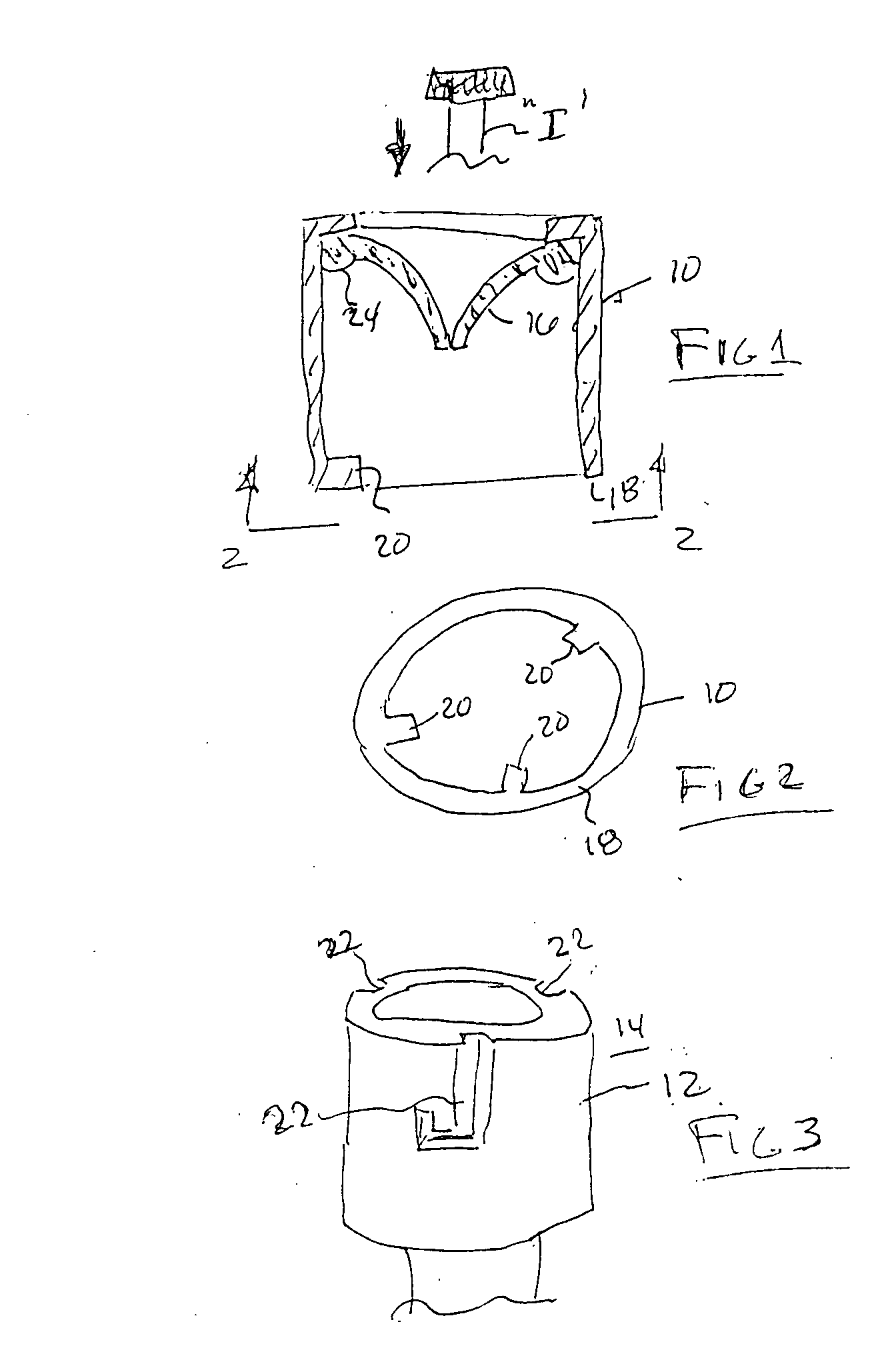
[0026] The present invention comprises in a first aspect thereof, a proximal cap 10, as shown in FIG. 1, arranged for securable attachment to the proximal end of a cannula 12, which comprises a trocar assembly 14 of the present invention. The cap 10 may have a flexible flap, slit or “duckbill” type valve 16 fitted therein. The cap 10 is preferably of cylindrical shape and has a distal edge 18. A plurality of inwardly directed spurs 20 are arranged within the distal edge 18 of the cap 10, as shown in FIGS. 1 and 2. The spurs 20 are circumferentially spaced so as to mate with and lock into a plurality of receiving grooves 22 in a “bayonet” manner on the proximal periphery of the cannula 12, as represented in FIG. 3. An operative surgical instrument “I” would then be introduced through this proximal valve 16 on the cannula 12. The valve 16 may in a further embodiment, have a soft compressable “O” ring 24 unitarily arranged about its proximal periphery, as represented in FIG. 1. The O-r...


PUM


Abstract

A cannula assembly for the maintenance of an operative pneumoperitoneum in a patient comprising an elongated cannula having a proximal end and a distal end. A removable valve is securely arranged in the proximal end of the cannula to provide a seal and minimize the escape of gas introduced into the patient's pneumoperitoneum when an operative instrument is passed therethrough.

Description

[0001] This application is a continuation-in-part application of our co-pending U.S. patent application Ser. No. 10 / 739,872, filed 18 Dec. 2003, which is a continuation-in-part application of U.S. patent application Ser. No. 10 / 441,149 filed 17th of May 2003, which is based upon and incorporates herein provisional patent application Ser. No. 60 / 461,149 filed 8 of Apr. 2003, each of which are incorporated herein by reference in their entirety.BACKGROUND OF THE INVENTION [0002] 1. Field of the Invention [0003] This invention relates to methods and apparatus of trocar devices and more specifically, arrangements to increase the efficiency of a pneumoseal (no seal) cannula when used in conjunction with a multitude of other various different ID sized cannulae. [0004] 2. Prior Art [0005] The primary goal of cannula seals for laparoscopic, or minimally invasive surgery is to maintain gaseous distention of the abdominal cavity adequately for an operative pneumoperitoneum. An operative pneumo...

Claims


Application Information

Patent Timeline
IPC IPC(8): A61B17/00A61B17/34A61B19/00
CPCA61B17/3421A61B17/3423A61B17/3462A61B2019/464A61B17/3498A61B2017/00265A61B17/3474A61B2090/064
Inventor CAMPBELL, MICHAEL J.HALGREN, DONALD N.HARTMAN, GEORGE A. J.PARKER, KENSTUBBS, JACK B.THOMPSON, RONALD J.
Owner IPTECH
Learn More