Embolic filtering devices

a filter device and emboli technology, applied in the field of emboli filtering devices, can solve the problems of emboli being released into the circulatory system, affecting the patient's health, and causing severe health problems, so as to prevent “splaying” and kinking of the guide wire. the effect of quick and easy removal

Inactive Publication Date: 2005-01-06
ABBOTT CARDIOVASCULAR
View PDF98 Cites 173 Cited by
  • Summary
  • Abstract
  • Description
  • Claims
  • Application Information

AI Technical Summary

Benefits of technology

[0015] The present invention provides a flexible self-expanding frame for use with an embolic filtering device designed to capture embolic debris created during the performance of a therapeutic interventional procedure, such as a balloon angioplasty or stenting procedure, in a body vessel. The present invention provides the physician with an embolic filtering device having the flexibility needed to be steered through tortuous anatomy, but yet possesses sufficient strength to hold open a filtering element against the wall of the body vessel for capturing embolic debris. The present invention provides sufficient flexibility without compromising the radiopacity characteristics of the filtering device. An embolic filtering device made in accordance with the present invention is relatively easy to deploy and has good flexibility and conformability to the patient's anatomy.
[0018] In some aspects, the present invention is directed to improvements relating to the mounting and positioning of the pair of half frames which cooperatively form the expandable frame of the embolic filter assembly. In one particular aspect of the present invention, each of the half frames includes a first control arm connected to a second control arm by a partial loop. The partial loop extends radially outward when placed in an expanded position so that a substantially circular loop is created by the two partial loops. The partial loops may include an articulation region which helps to distribute strain which can be developed when the half frame move between the expanded and collapsed positions. The articulation region also enhances the bendability of the half frames. In one particular embodiment, the articulation region can take on a D-shaped curve which extends from the apex of the partial loop. The placement and angulation of the articulation region on the partial loops can be varied to achieve the desired amount of bending and flexibility needed for a particular material or wire diameter.
[0019] In another aspect of the present invention, the half frames can be mounted onto a filter support structure which allows the composite frame and filter element to rotate relative to the guide wire without twisting the filter. In one particular aspect, the filter support structure can be a coiled wire which provides excellent bendability to the assembly of components. The filter support structure can be mounted between a pair of fittings located on the guide wire which limit or eliminate relative longitudinal movement between the filter assembly and the guide wire.
[0020] In another aspect of the present invention, the frame includes a first and a second control arm which are attached to a pair of partial loops that expand to form a composite circular loop for maintaining the filter element in position against the wall of the body vessel. The pair of partial loops can include articulation regions and strain distributing struts which increase flexibility and bendability at various bend points on the frame. In a variation of this frame, a set of distal control arms can extend from the connection of the first and second control arms and the partial loops to a distal mounting region. This second set of distal control arms can support the filter element and help prevent the filter element from rotating differently, i.e. twisting, to that of the frame.
[0022] In another aspect of the present invention, a special torque device can be utilized in conjunction with a peel-away delivery sheath which is utilized to deliver the collapsed embolic filter assembly into the patient's vasculature. The special torque device includes a side port for receiving the proximal end of the delivery sheath through which the physician pulls the sheath to cause the sheath to be split by the guide wire. As a result, the delivery sheath can be quickly and easily removed from the guide wire once the embolic filtering assembly has been positioned in the target location in the patient. One embodiment of the special torque device is a clip-on component which can be attached to a conventional torque device and includes a side port that causes the delivery sheath to be split as it is being removed from the guide wire. In another aspect of the torque device, an arm extension helps to maintain the delivery sheath on the guide wire along the same axis until the delivery sheath is placed in a side port located on the device. The extension arm helps to prevent “splaying” and kinking of the guide wire as the delivery sheath is being “stripped” or “peeled” from the guide wire.

Problems solved by technology

However, there is one common problem which can become associated with all of these non-surgical procedures, namely, the potential release of embolic debris into the bloodstream that can occlude distal vasculature and cause significant health problems to the patient.
Additionally, while complete vaporization of plaque is the intended goal during laser angioplasty, sometimes particles are not fully vaporized and enter the bloodstream.
When any of the above-described procedures are performed in the carotid arteries, the release of emboli into the circulatory system can be extremely dangerous and sometimes fatal to the patient.
Debris carried by the bloodstream to distal vessels of the brain can cause cerebral vessels to occlude, resulting in a stroke, and in some cases, death.
Therefore, although cerebral percutaneous transluminal angioplasty has been performed in the past, the number of procedures performed has been somewhat limited due to the justifiable fear of an embolic stroke occurring should embolic debris enter the bloodstream and block vital downstream blood passages.
However, it is often difficult to control the size of the fragments which are formed, and the potential risk of vessel occlusion still exists, making such a procedure in the carotid arteries a high-risk proposition.
However, there can be complications associated with such systems if the vacuum catheter does not remove all of the embolic material from the bloodstream.
Also, a powerful suction could cause trauma to the patient's vasculature.
While a filter can be effective in capturing embolic material, the filter still needs to be collapsed and removed from the vessel.
During this step, there is a possibility that trapped embolic debris can backflow through the inlet opening of the filter and enter the bloodstream as the filtering system is being collapsed and removed from the patient.
Also, while it is beneficial if the area of treatment is located in a substantially straight portion of the patient's vasculature, sometimes the area of treatment is at a curved portion of the body vessel which can be problematic to the physician when deploying the expandable filter.
If the expandable filter portion is too stiff, it is possible that the filter may not fully deploy within the curved portion of the body vessel.
As a result, gaps between the filter and vessel wall can be formed which may permit some embolic debris to pass therethrough.
However, the use of thin material often can reduce the radiopacity of the expandable filter, often making it difficult for the physician to visualize the filter during deployment.
Visualization of filters made from a nickel-titanium alloy, which has relatively low radiopacity as compared to other metallic materials, is also difficult during fluoroscopy.
Conversely, the use of thicker materials, which can promote radiopacity of the expandable filter, usually reduces its flexibility, which may impair the deliverability of the expandable filter within the patient.

Method used


Image

  • Embolic filtering devices
  • Embolic filtering devices
  • Embolic filtering devices

Examples


Embodiment Construction

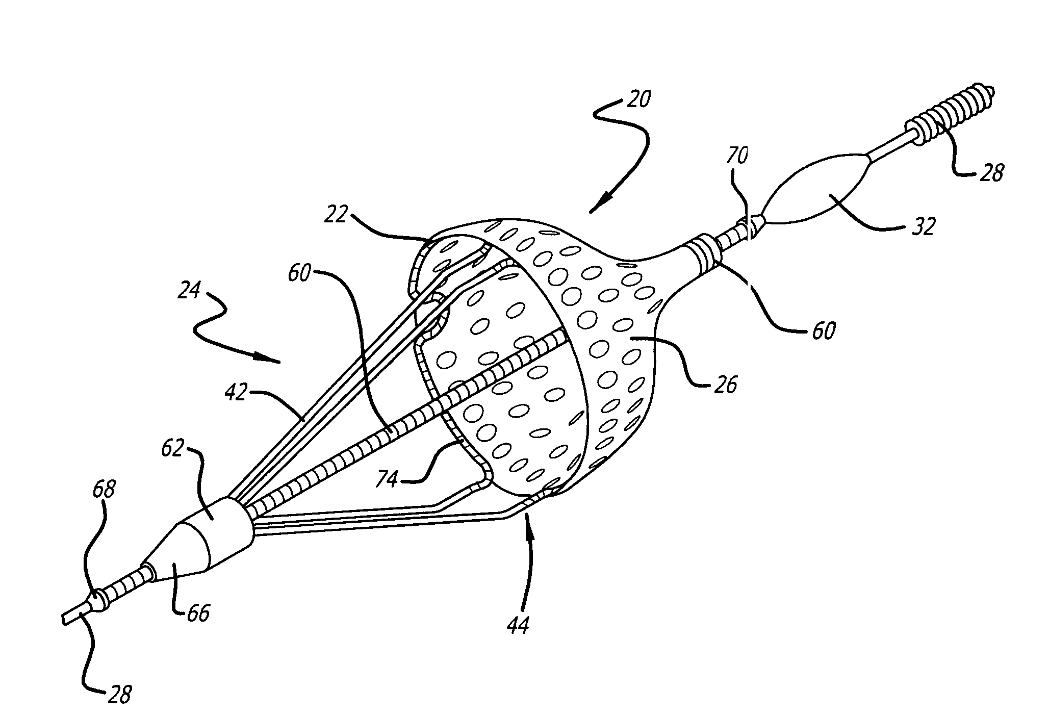
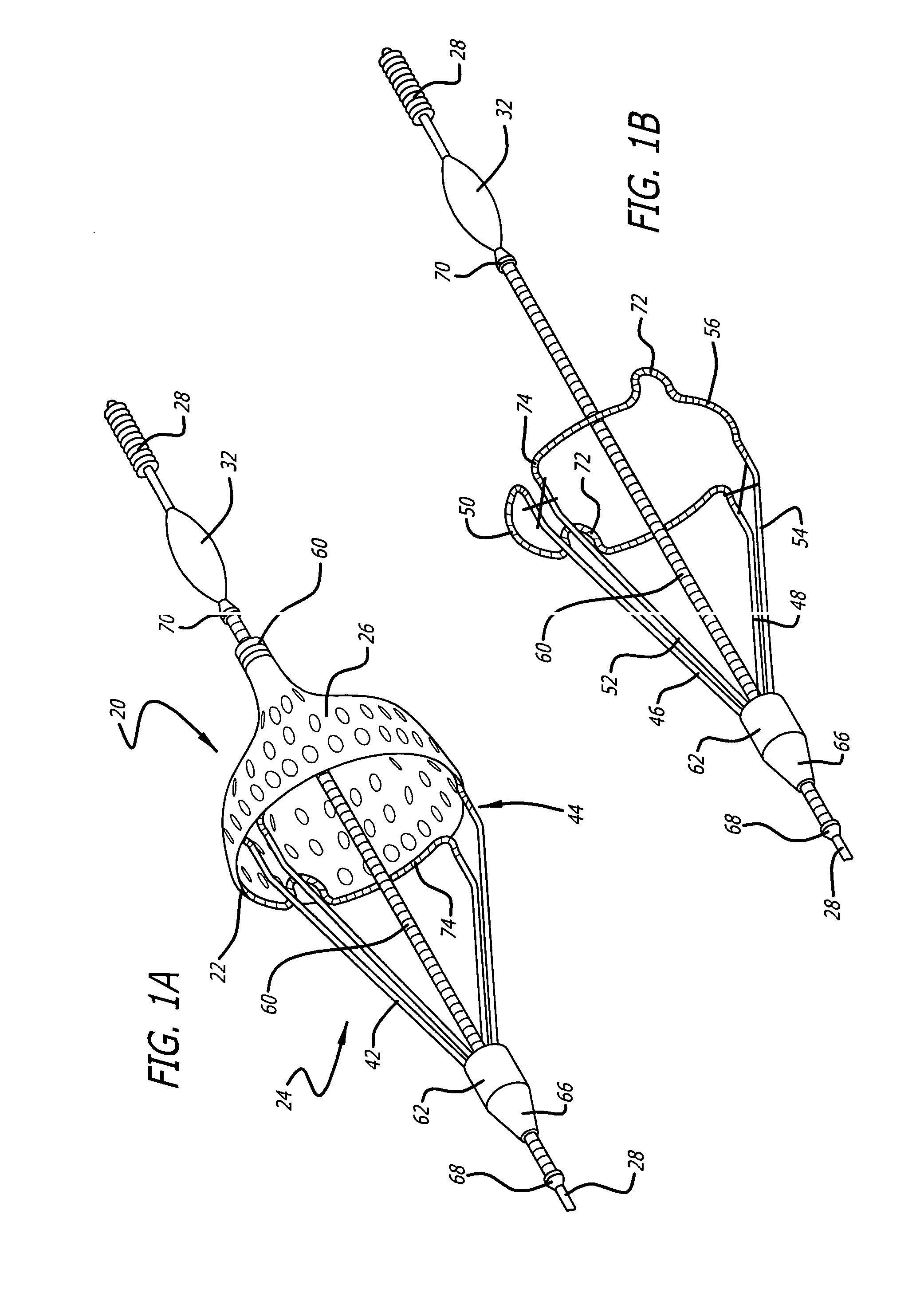
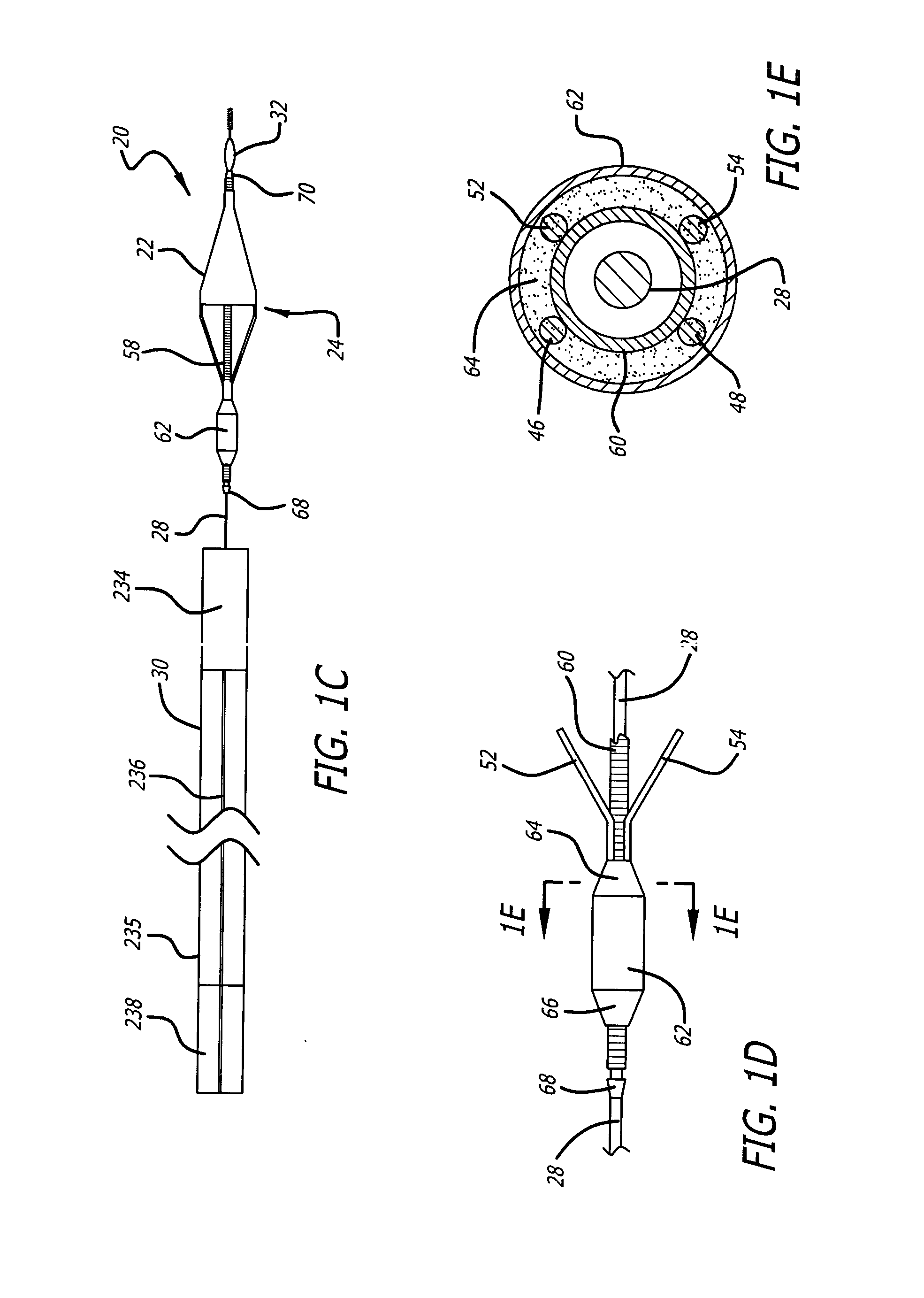
[0064] Turning now to the drawings, in which like reference numerals represent like or corresponding elements in the drawings, FIGS. 1A, 1B and 1C illustrate one particular embodiment of an embolic filtering device 20 incorporating features of the present invention. This embolic filtering device 20 is designed to capture embolic debris which may be created and released into a body vessel during, for example, an interventional procedure. The embolic filtering device 20 includes an expandable filter assembly 22 having a self-expanding frame 24 (also referred to as a basket) and a filter element 26 attached thereto. In this particular embodiment, the expandable filter assembly 22 is rotatably mounted near the distal end of an elongated tubular or solid shaft, such as a steerable guide wire 28. A restraining or delivery sheath 30 (see FIGS. 1C and 2A) extends coaxially along the guide wire 28 in order to maintain the expandable filter assembly 22 in its unexpanded, delivery position unt...


PUM


Abstract

An expandable frame for an embolic filtering device used to capture embolic debris in a body vessel includes a first half frame having a first control arm connected to a second control arm by a partial loop and a second half frame having a first control arm connected to a second control arm by a partial loop. The partial loops cooperatively form a composite loop for attachment of a filtering element which will expand in the body vessel to capture embolic debris entrained in the fluid of the vessel. The expandable frame and filtering element can be mounted on a filter support structure, such as a coiled wire, and mounted on a guide wire. The expandable frames include an articulation region which helps to distribute the strain which can be developed when the frame moves between an expanded and deployed position. The expandable frame may include further strain distributing bends which help distribute strain and increase the bendability of the frame. A modified torque device with extension arm prevents guide wire damage, prevents distal propagation of the peeling action and facilitates filter deployment during operation.

Description

CROSS-REFERENCE TO RELATED APPLICATION [0001] This application is a continuation-in-part of application Ser. No. 10 / 377,285 filed Feb. 27, 2003, which is assigned to the same Assignee as the present application.BACKGROUND OF THE INVENTION [0002] The present invention relates generally to filtering devices and systems which can be used, for example, when an interventional procedure is being performed in a stenosed or occluded region of a body vessel to capture embolic material that may be created and released into the body fluid during the procedure. The present invention is more particularly directed to an embolic filtering device made with a self-expanding frame (also referred to as a basket or cage) having good flexibility and bendability to reach often tortuous areas of treatment, along with special torque devices that are used to facilitate the rapid removal of a peel-away delivery sheath used to position the filtering device within the patient's vasculature. [0003] Numerous pro...

Claims


Application Information

Patent Timeline
Patent Type & Authority Applications(United States)
IPC IPC(8): A61F2/01A61F2/06A61M25/06
CPCA61F2/013A61F2/97A61F2002/011A61F2230/0006A61F2230/008A61F2002/018A61F2002/015A61F2/011A61F2/0108
Inventor BOYLE, WILLIAM J.PAPP, JOHN E.PETERSON, CHARLES R.MULLER, PAUL F.SCHWARTEN, DONALDLIND, KATHERN J.
Owner ABBOTT CARDIOVASCULAR
Why Eureka
Try Eureka