Shoe suspension system

a suspension system and spring technology, applied in the field of boots and shoes, can solve the problems of inability to permit users to concurrently, ineffective and imprecise structures, and high cost and unreliability of spring shoes, and achieve the effects of optimum control, safety and agility, optimum traction stability, and mild internal roll capability

Active Publication Date: 2005-01-13
PERENICH STEPHEN
View PDF12 Cites 58 Cited by
  • Summary
  • Abstract
  • Description
  • Claims
  • Application Information

AI Technical Summary

Benefits of technology

[0025] (1) Providing an upper and lower sole which are parallel to each other wherein the lower sole moves away from the upper sole in a substantially perpendicular direction. This permits optimum control, safety, and agility, energy transfer from the heel to the ball of the foot, and natural walking and running motion.
[0026] (2) Forming the lower sole to correspond to the anatomy of the foot and ankle of the user to allow optimum traction stability, control and safety. Wherein the lower sole can include a rigid inner mid-sole and a flexible outer mid and heel sole to provide mild internal roll capability.
[0027] (3) Providing structure that maintains a longitudinally parallel posture between the upper and lower toe-sole during mid-stride compression, forward roll and toe-sole lift off, thereby allowing users optimum balance, control, traction and safety.
[0028] (4) Limiting the maximum and minimum opening of the soles while at the same time, softening the impact of the foot as the sole reaches its full compression, thereby increasing control, stability, safety and comfort.
[0029] (5) Providing in embodiments in which the compressed spring load significantly exceeds a user's body weight, a system to hold and release (“HRS”) the energy stored in the springs at an optimum time during accelerating, cruising or while decelerating. Utilizing this system, the performance benefit is roughly proportionate to the stored energy loads in excess of the user's body weight. Thus, this structure allows users to more than double their running stride and jumping performance compared to similar models without this system. This system is optimally designed in that it delivers: 1) Excellent control, 2) high running and jumping performance, 3) safe deceleration / stopping, 4) a greater measure of running efficiency, allowing users to run longer distances while burning the same calories, 5) a completely natural running motion, which in turn, further increases stability, reduces fatigue, and further increases performance, and 6) a safety default to disengage the system if mechanical failure occurs.

Problems solved by technology

Spring shoes thus far have not been entirely satisfactory in that they have not permitted users to concurrently experience: 1) traction, control, agility and safety comparable to non-spring-loaded footwear, 2) comparable impact absorption and 3) true energy conservation (i.e. storage and return) during walking and running.
Spring shoes that have attempted to address the energy conservation issued have employed either very complex, expensive and unreliable structures or ineffective and imprecise structures.
No non-fuel-propelled footwear devices has thus far allowed users to increase their maximum running speed.
While some have allowed an increase in stride-length, their unnatural use and / or excessive weight prevent users from running any faster than with standard running shoes.

Method used


Image

  • Shoe suspension system
  • Shoe suspension system
  • Shoe suspension system

Examples


embodiment 1

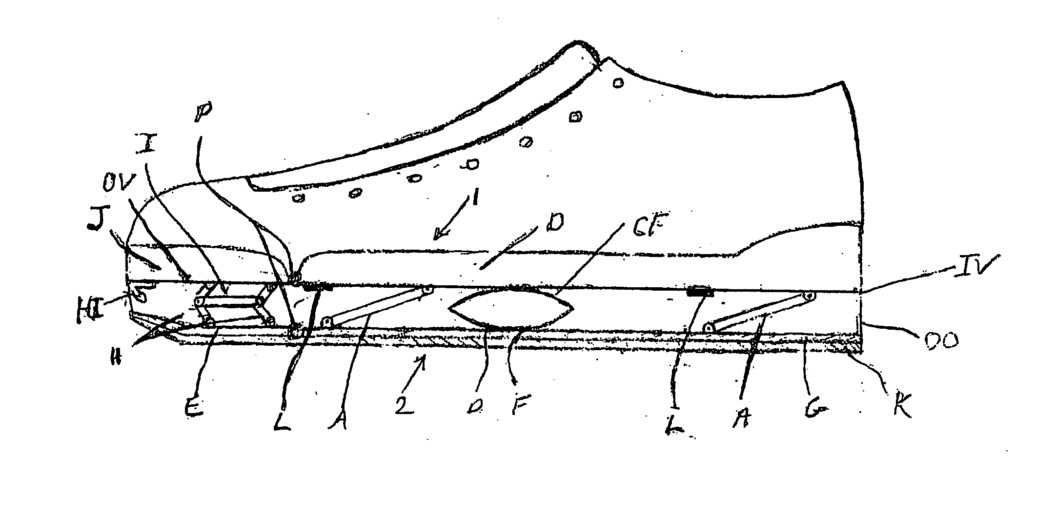
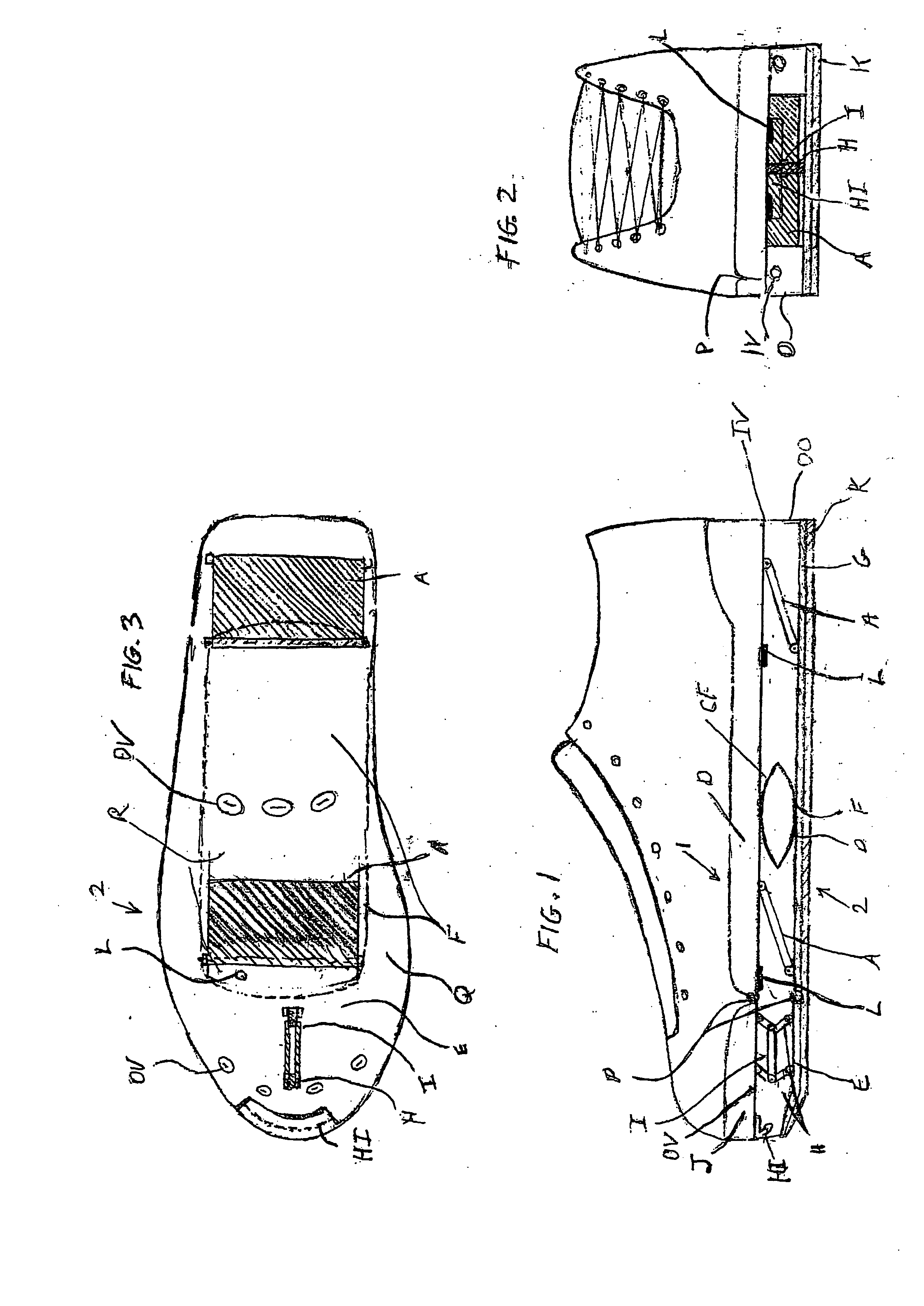
[0114] The lower sole (2) of embodiment 1 is patterned after the anatomy of the foot and ankle allowing users optimum traction, stability, control and safety. The lower sole provides for an integrated lower toe sole portion (E), lower mid sole portion (F), flexible outer portion (Q) of the mid sole (F) and lower heel sole (G) provides mild lateral roll capability.

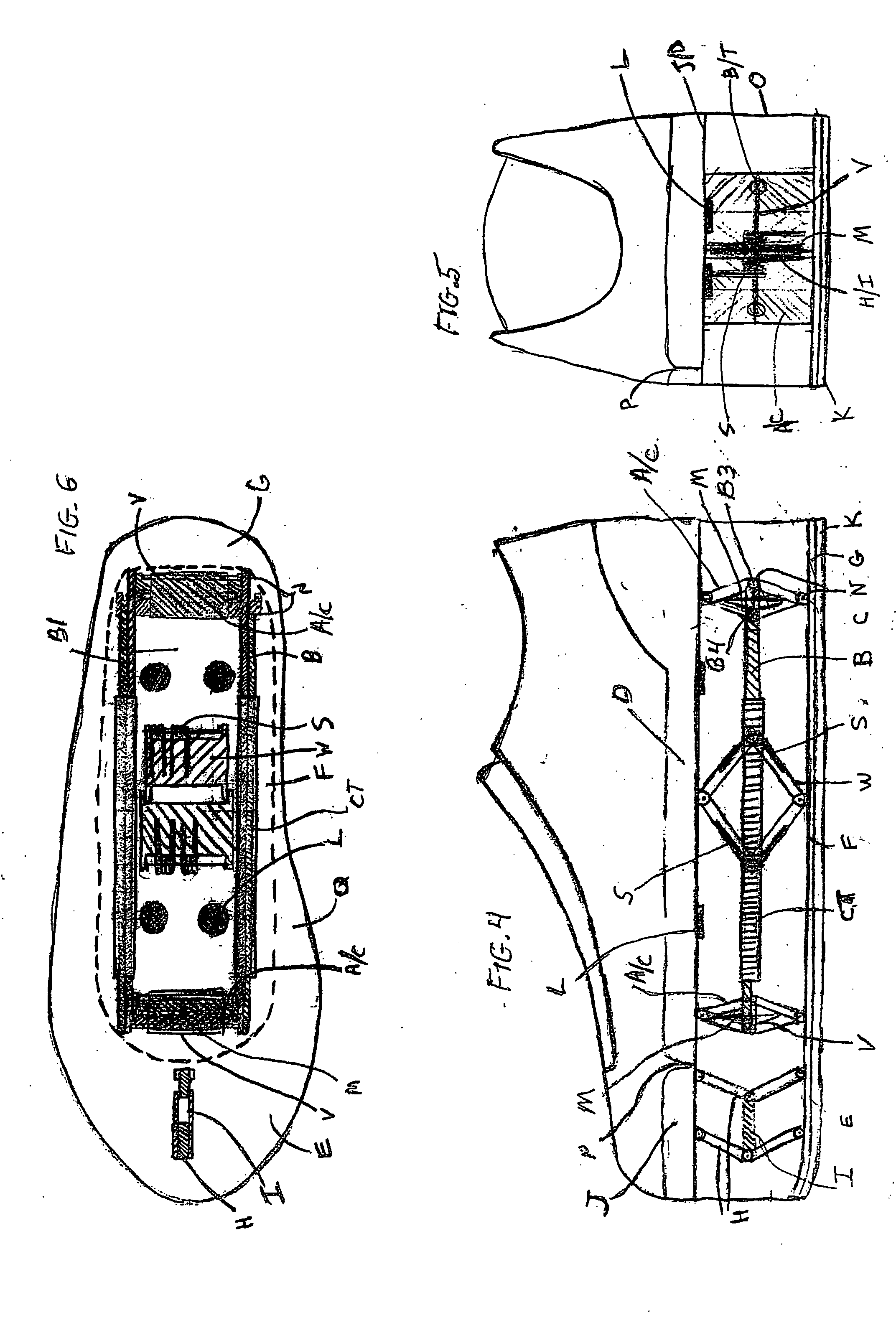
[0115] Embodiment 2 is a high performance running shoe for straight line running. Embodiment 2 as shown in FIGS. 4-6, also includes, as in embodiment 1, an upper sole (1), a lower sole (2), upper toe sole portion (J), upper mid heel sole portion (D), tread (K), a lower rigid inner section (F), a lower flexible outer section (Q), and a secondary tandem hinge (H) engaged between the lower sole (2) and the upper toe sole portion (J), and stops (L). The upper sole (1) includes a flex point (P) connecting an upper toe sole portion (J) to the upper mid / heel portion (D). These elements serve substantially the same purpose as the e...

embodiment 3

[0120] In embodiment 3, the lower mid-sole (F) consists of an inflexible (e.g. steel), rectangular plate. The lower sole is connected to the tandem hinges by longitudinal pivots that allow lateral pivoting of the lower sole. A lateral support bumper (T) is inserted between the lower mid-sole (F) and the tandem hinge arm's hinge pin (X). An alternative structure can be used comprising of an inflexible rod connected at the ends to lower toe and heel soles via front and rear ball joints. This alternate structure also specifies a coil spring (CS) above the ball joint. The purpose of these structures is to: 1) provide traction to the user during mid-stride and 2) enhance balance and stability during mid-stride in a straight-line or in a turn.

[0121] All the primary and secondary tandem and opposing tandem hinges' (A), (A / C) and (H) have lower plates that are triangular in shape with their apex positioned at the lower toe / mid / heel soles (E), (F) and (G) where the apex attaches to the topsi...

embodiment 4

[0127] In the high performance application of embodiment 4, the compressed spring load significantly exceeds a user's body weight. This system holds and releases (“HRS”) the energy stored in the springs at an optimum interval during accelerating, cruising or while decelerating. Utilizing this system, the performance benefit is roughly proportionate to the stored energy loads in excess of the user's body weight. Thus, this structure allows users to more than double their running stride and jumping performance compared to similar Embodiments without this system. This system is optimally designed in that it delivers: 1) Excellent control, 2) High running and jumping performance, 3) Safe deceleration / stopping, 4) A greater measure of running efficiency, allowing users to run longer distances while burning the same calories, 5) A completely natural running motion, which in-turn, further increases stability, reduces fatigue, and further increases performance and 6) A safety default to dis...


PUM

PropertyMeasurementUnit
diameteraaaaaaaaaa
diameteraaaaaaaaaa
diameteraaaaaaaaaa

Abstract

A shoe suspension system for use with a shoe or boot having an upper and lower sole. The system includes a first tandem hinge pivotally engaged between the upper toe sole and the lower toe sole which opens and closes parallel to the longitudinal axis of the shoe a plurality of tandem hinges pivotally engaged between the upper mid heel sole and the lower sole which also open and close parallel to the longitudinal axis of the shoe and return springs engaged between the upper mid heel sole and the lower sole.

Description

CROSS-REFERENCE TO RELATED APPLICATIONS [0001] This application is a continuation of non-provisional application Ser. No. 10 / 717,915 of prior U.S. provisional application No. 60 / 427,959, filed Nov. 21, 2002, and 60 / 491,260, filed Jul. 31, 2003. The entire contents of all the above applications are hereby incorporated by reference.BACKGROUND OF THE INVENTION [0002] 1. Technical Field [0003] The present invention relates to the general art of boots and shoes, and to the particular field of impact absorbing and energy return mechanisms associated with boots and shoes. [0004] 2. Prior Art [0005] It has long been known, that when people walk, jog, or run, a significant percentage of their forward kinetic energy is wasted and lost. This loss results in shock which is caused by a person's foot impacting with the ground. How to store and release this energy loss is the overall problem. Existing devices involve an assemblage of different types of springs adhered to the base of a shoe. Genera...

Claims


Application Information

Patent Timeline
Patent Type & Authority Applications(United States)
IPC IPC(8): A43B13/14A43B13/18
CPCA43B13/181A43B13/141
Inventor PERENICH, STEPHEN
Owner PERENICH STEPHEN
Why Eureka
Try Eureka