Heavy-duty pneumatic tire

a pneumatic tire and heavy-duty technology, applied in the direction of vehicle components, transportation and packaging, non-skid devices, etc., can solve the problems of unavoidable significant reduction of conspicuous heel-and-toe wear in the shoulder block. , to achieve the effect of reducing the occurrence of heel-and-toe wear, good drainage and traction performan

Active Publication Date: 2005-01-13
YOKOHAMA RUBBER CO LTD
View PDF7 Cites 10 Cited by
  • Summary
  • Abstract
  • Description
  • Claims
  • Application Information

AI Technical Summary

Benefits of technology

[0005] An object of the present invention is to provide a heavy-duty pneumatic tire which can suppress the occurrence of heel-and-toe wear in the shoulder blocks while maintaining good drainage and traction performance through the final stage of the wear life.

Problems solved by technology

In a heavy-duty pneumatic tire, putting importance on the traction performance, which includes a number of lug grooves extended in the tire width direction in the tread portion, a problem of heel-and-toe wear occurring in the shoulder blocks has been conspicuous.
Accordingly, it is likely that the heel-and-toe wear occurs.
Consequently, significant reduction of the drainage and the traction performance was unavoidable after the middle stage of the wear life.

Method used


Image

  • Heavy-duty pneumatic tire
  • Heavy-duty pneumatic tire
  • Heavy-duty pneumatic tire

Examples


Embodiment Construction

[0014] A description will be given of a configuration of the present invention in detail below with reference to the accompanying drawings.

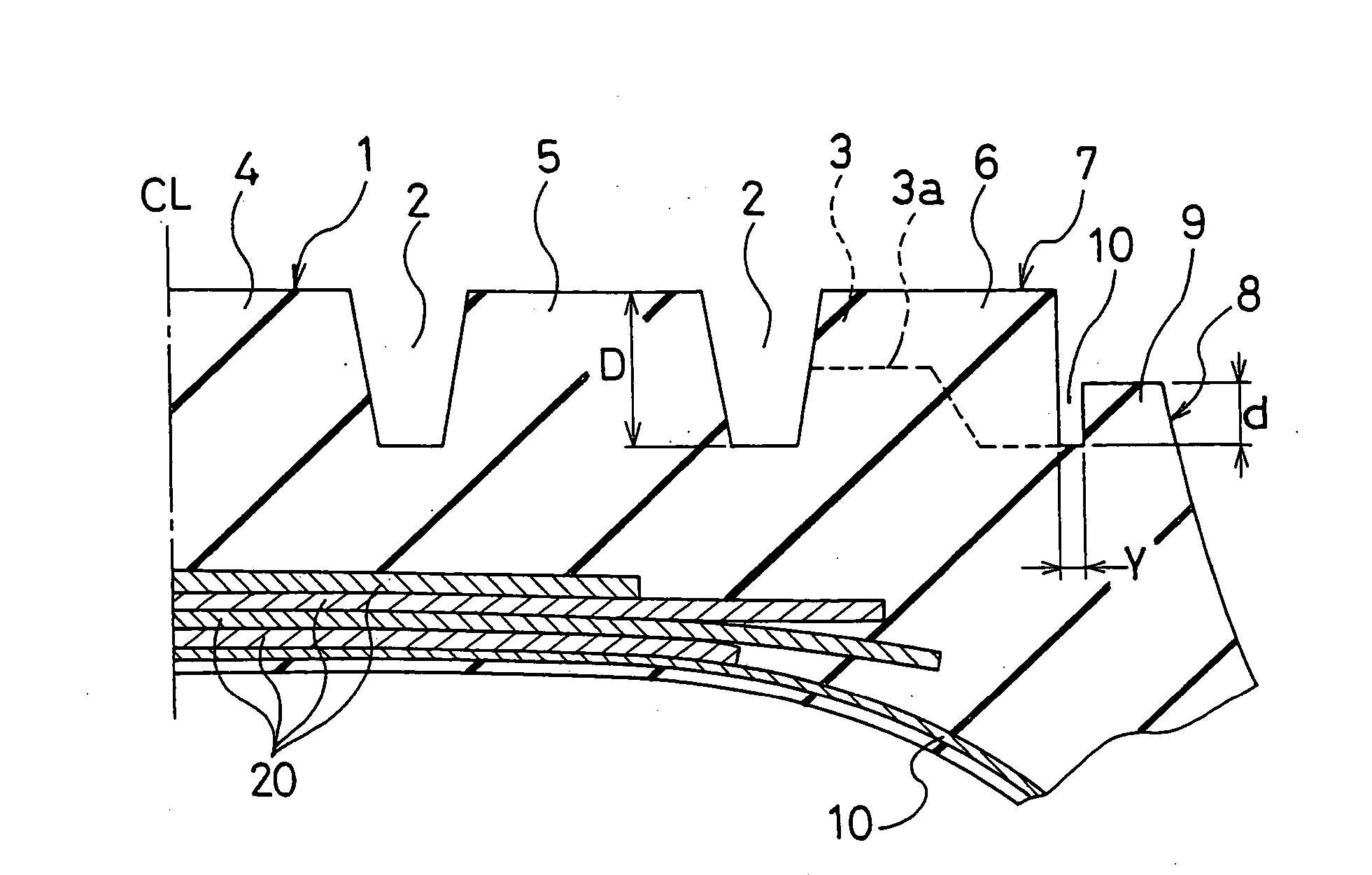
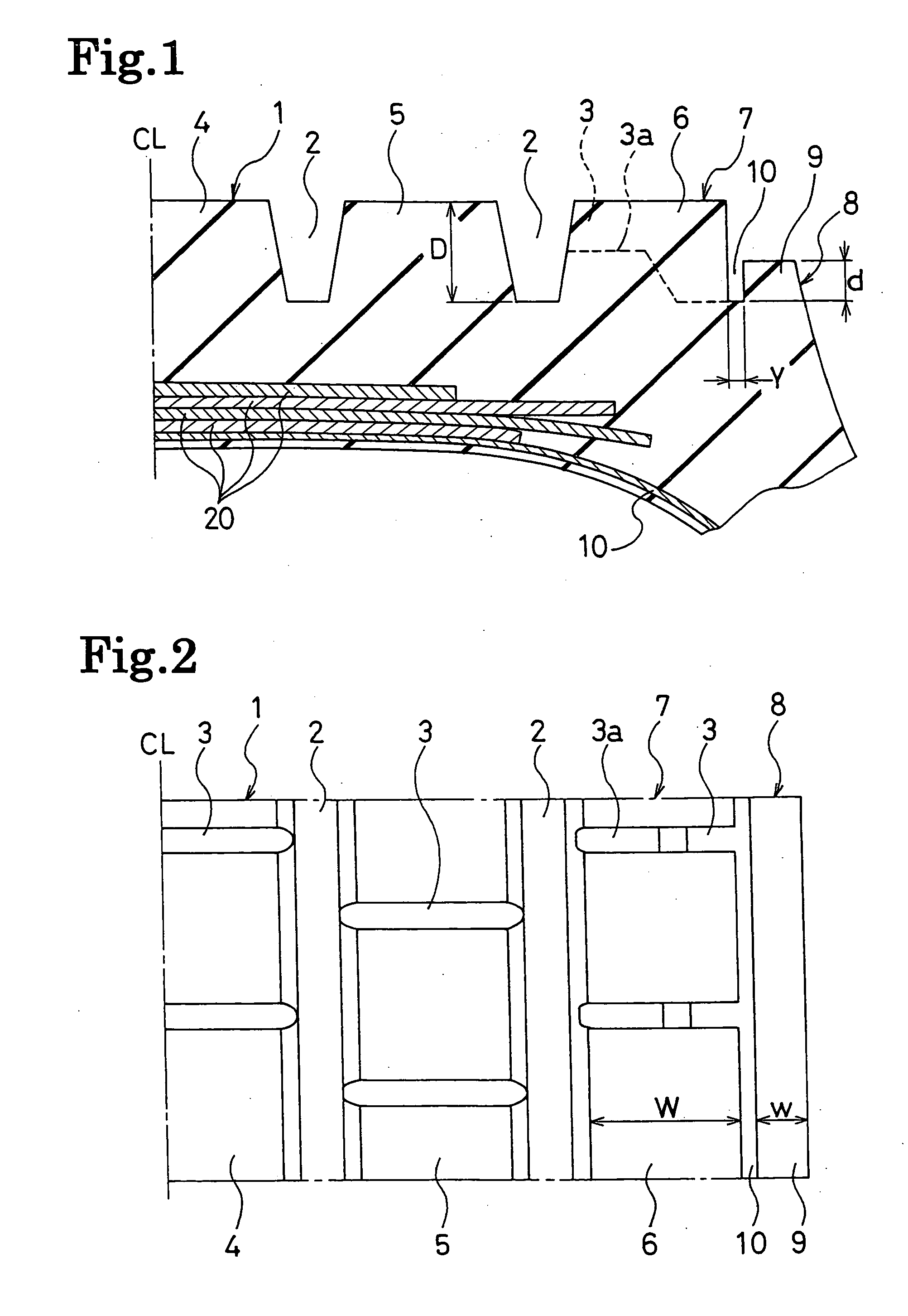
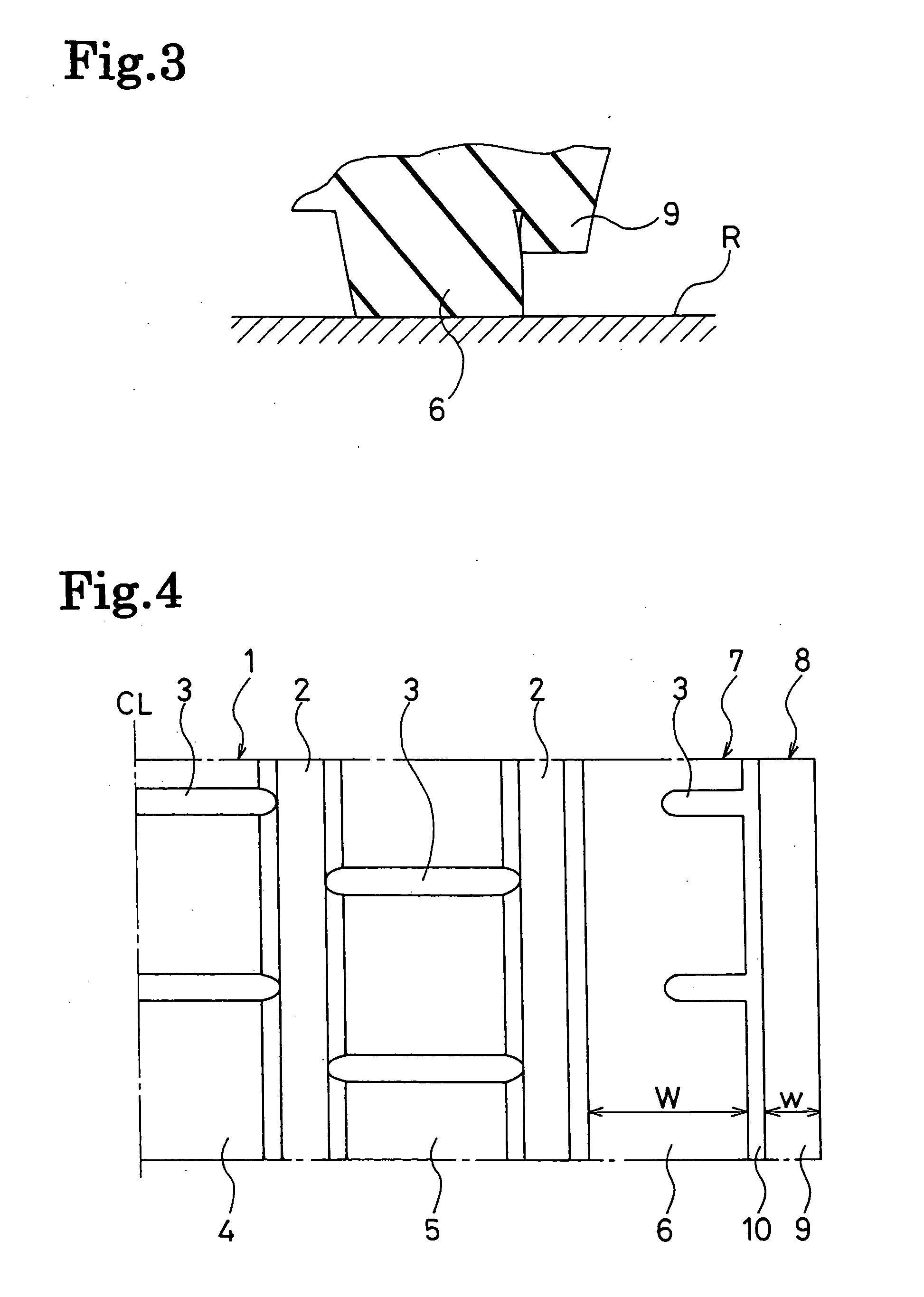
[0015]FIGS. 1 and 2 show a main portion of a pneumatic tire according to an embodiment of the present invention.

[0016] In FIGS. 1 and 2, a reference code CL denotes the tire center line. Reference numerals 11 and 12 denote a carcass layer and a belt layer, respectively. The internal structure of the tire including the carcass layer 11 and the belt layer 12 is not particularly limited.

[0017] As shown in FIGS. 1 and 2, a plurality of main grooves 2 extended in the tire circumferential direction and a plurality of lug grooves 3 extended in the tire width direction are formed in a tread portion 1. The three rows of blocks are formed, by the main and lug grooves, from the center side to the shoulder side in the tread portion 1. Specifically, a plurality of blocks 4 are formed in the tire circumferential direction on the center side of the tread por...


PUM


Abstract

A heavy-duty pneumatic tire designed to suppress the occurrence of heel-and-toe wear in the shoulder blocks while maintaining good drainage and traction performance through the final stage of the wear life. In this heavy-duty pneumatic tire, whose shoulder portion is divided into a plurality of shoulder blocks in the tire circumferential direction, and wherein the depth of the lug groove between each two adjacent of the shoulder blocks is set to be equal to the depth of main the grooves, a non-contact rib is provided, in a serial configuration in the tire circumferential direction, to a buttress portion outside a ground contact width, so as to come into contact with the side faces of the shoulder blocks in the state that the tire is in contact with the ground with a specified inflation pressure and a specified load.

Description

BACKGROUND OF THE INVENTION [0001] The present invention relates to a heavy-duty pneumatic tire used for trucks, buses, and the like. Specifically, the present invention relates to a heavy-duty pneumatic tire which suppresses the occurrence of heel-and-toe wear in the shoulder blocks while maintaining the good drainage and traction performance through the final stage of the wear life. [0002] In recent years, heavy-duty pneumatic tires are increasingly used under conditions of high speed oriented running. In a heavy-duty pneumatic tire, putting importance on the traction performance, which includes a number of lug grooves extended in the tire width direction in the tread portion, a problem of heel-and-toe wear occurring in the shoulder blocks has been conspicuous. In particular, in the case that lug grooves with a depth equal to that of the main grooves are provided to the shoulder portion in order to maintain the drainage and traction performance through the final stage of the wear ...

Claims


Application Information

Patent Timeline
Patent Type & Authority Applications(United States)
IPC IPC(8): B60C11/01B60C11/04B60C11/11B60C11/13
CPCB60C11/01B60C11/0306B60C2011/013B60C11/13B60C11/11
Inventor OOYAMA, TOSHIRO
Owner YOKOHAMA RUBBER CO LTD
Why Eureka
Try Eureka