Locking and removable step

Inactive Publication Date: 2005-01-13
TERZINI ROBERT
View PDF8 Cites 11 Cited by
  • Summary
  • Abstract
  • Description
  • Claims
  • Application Information

AI Technical Summary

Benefits of technology

[0016] Thus it is an object of the present invention to provide an easy to use tool which supports a weight.
[0017] It is a further object of the present invention to provide a tool that is easy to stabilize on a fixed vertical beam.
[0018] It is a further object of the present invention to provide a tool that is easy to attach and remove from a fixed beam.
[0019]

Problems solved by technology

It is often time consuming and cumbersome to locate and transport a ladder to the appropriate location.
Chairs and paint cans may not provide the required stability or support for the worker and may also be difficult to locate.
This is very cumbersome and prevents the user from using the tool with a fixed beam, an application that is very applicable for a step tool.
Many tasks needed to be performed during construction are very difficult to perform alone.
This i

Method used


Image

  • Locking and removable step
  • Locking and removable step
  • Locking and removable step

Examples


Embodiment Construction

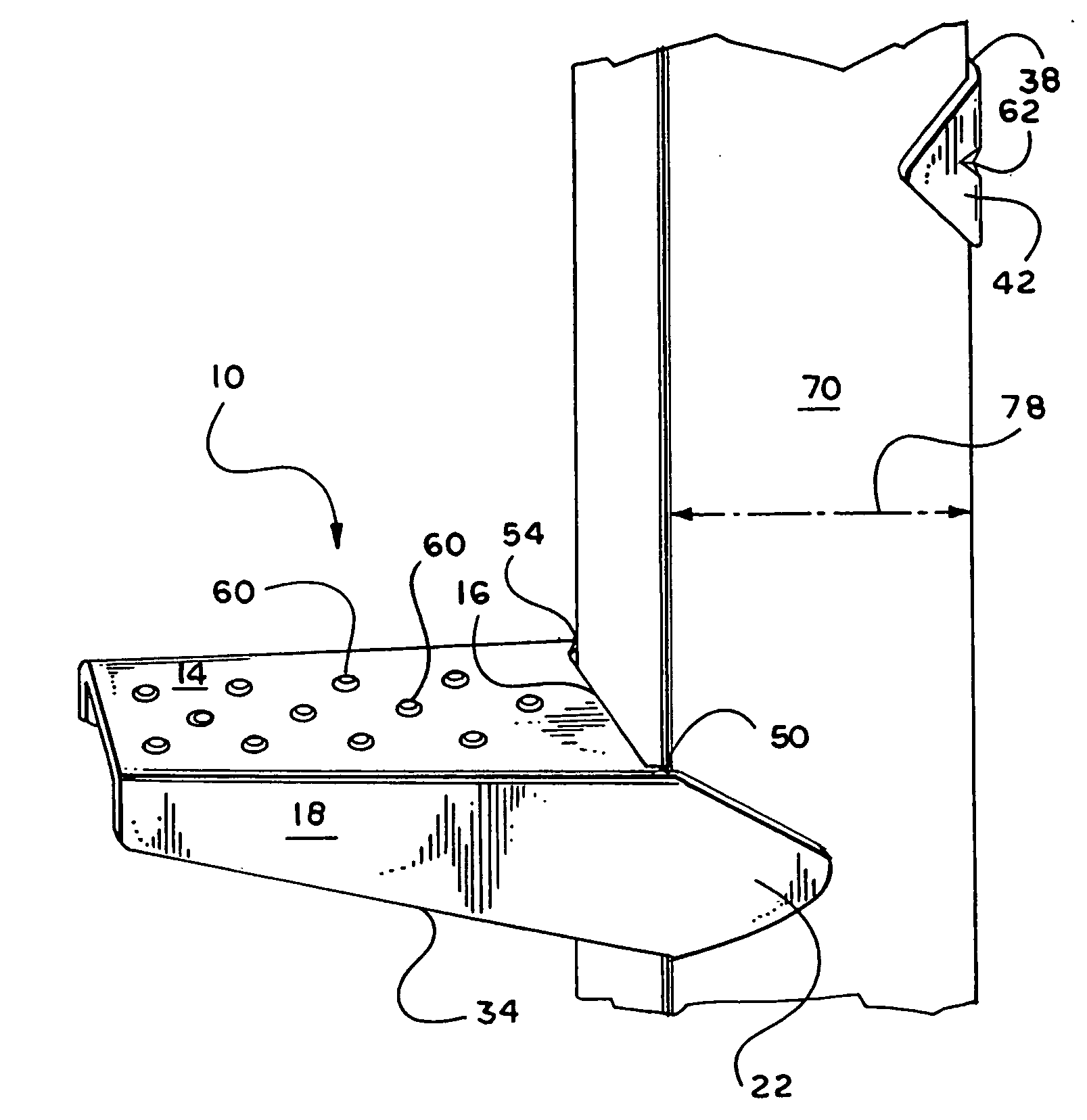
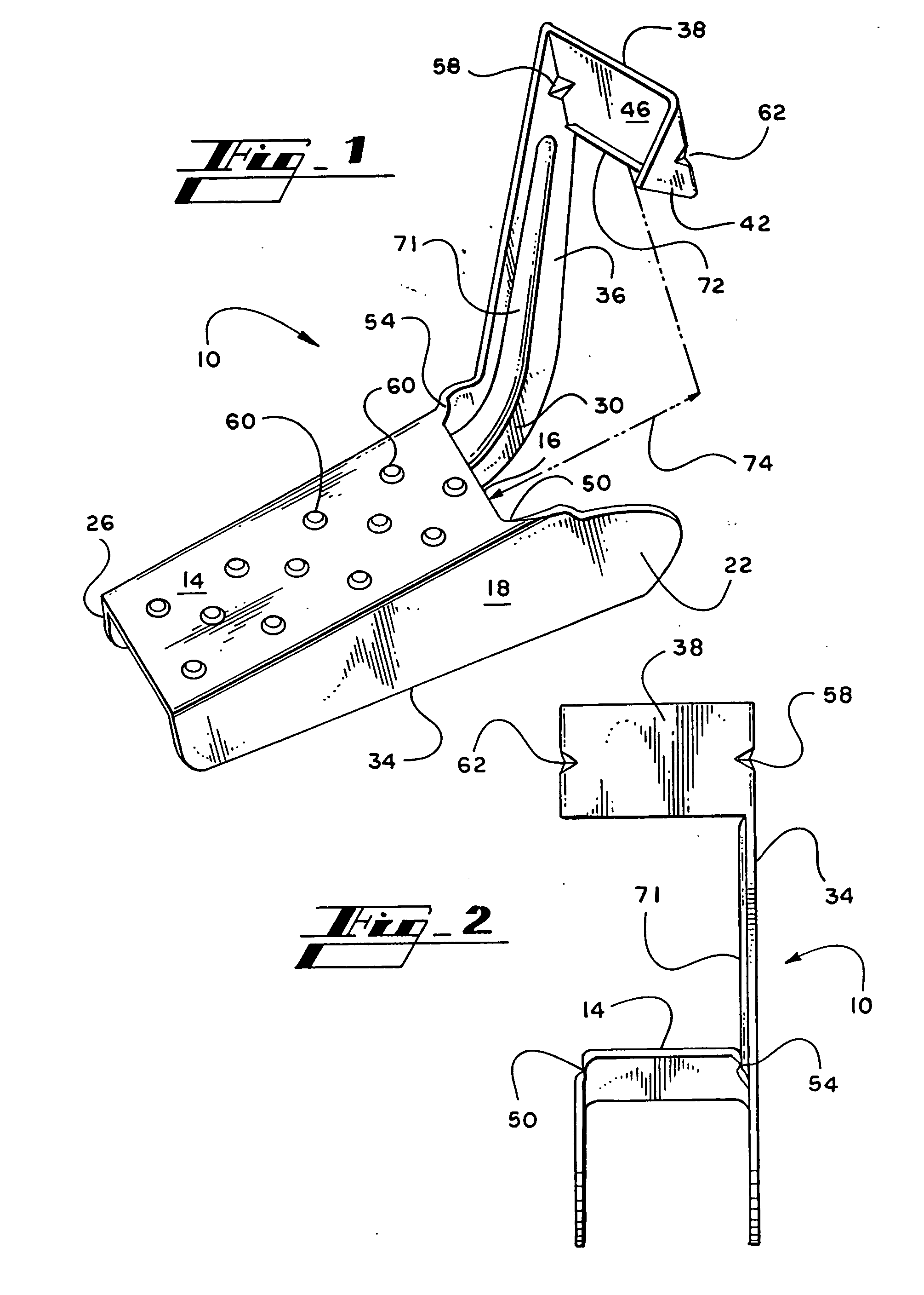
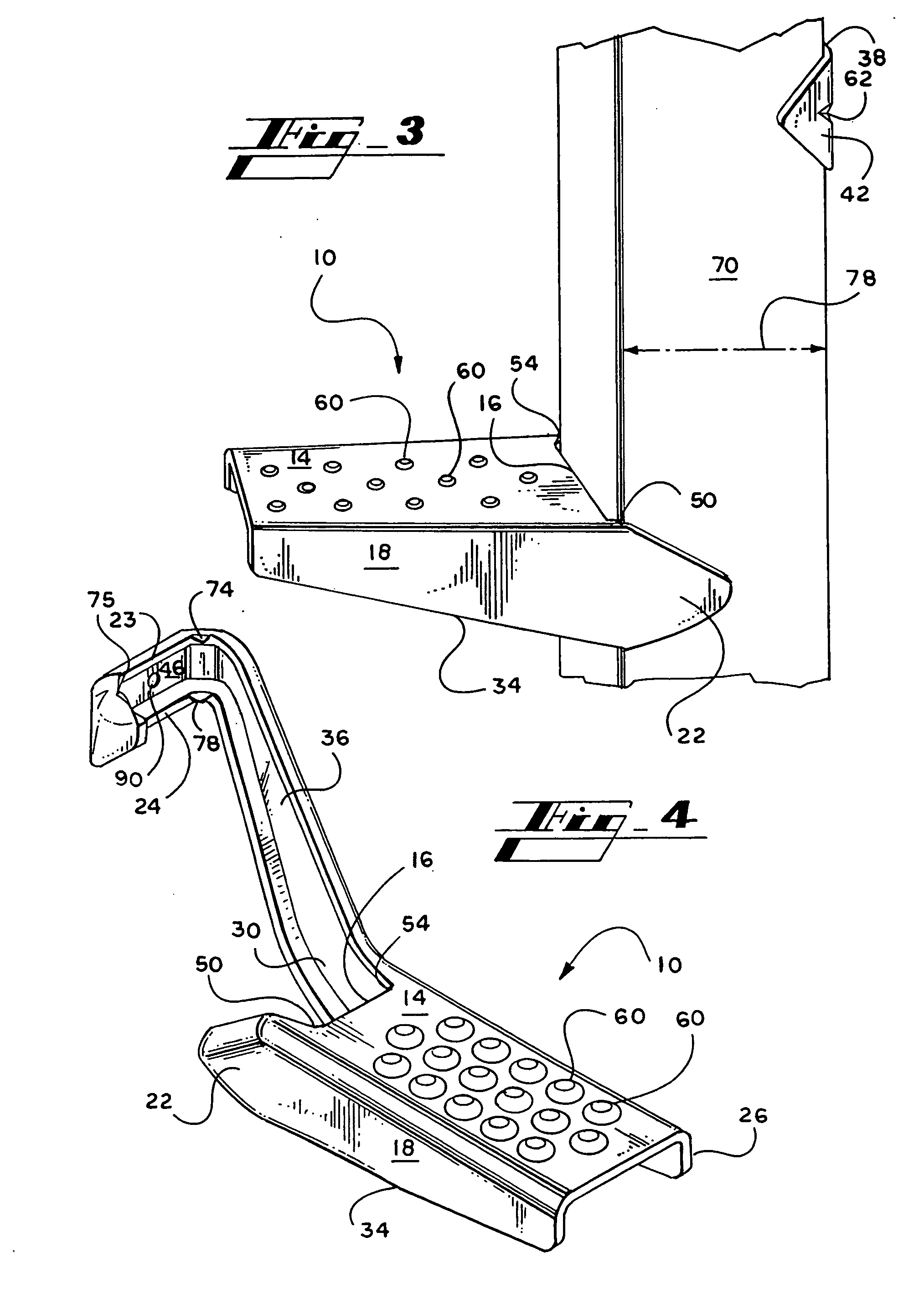
[0050] Referring now in more detail to the drawings, in which like numerals refer to like parts throughout the several views, FIG. 1 shows a pictorial view of a tool 10 for attaching to a four-sided wooden structural beam of the type used commonly in construction and supporting a person above the floor. With reference to FIG. 1, the tool 10 has an upper surface 14. The upper surface 14 is substantially rectangular in shape. A first side wall 18 extends vertically downward from a first side edge of the upper surface 14. The side wall 18 extends beyond a rear edge 16 of the upper surface 14, forming a side wall extension 22. A second side wall 26 extends vertically downward from a second side edge of the upper surface 14. A side wall extension 30 extends beyond the rear edge 16 of the upper surface 14. The two side walls 18, 26 are the same dimensions, each having a flat bottom edge 34 upon which the tool 10 can rest when placed on a flat surface. The rear edge 16 of the upper surface...


PUM


Abstract

The present invention is an easy to use device that attaches to a beam. The device may be used as a step for a user to stand on and attain elevation. The device may be used in combination to form a scaffold or a platform. The device is a tool having an upper surface with tapered ribs located on the back edge of the upper surface, a vertical member, and a collar. When the tool is placed around a beam and downward force applied to the tool, the ribs engage a first side of the beam and the collar engages the opposite side of the beam forming a lever. The tool is locked in place and the user is free to stand on it for support and elevation.

Description

RELATED APPLICATIONS [0001] This application is a continuation in part of U.S. application Ser. No. 09 / 667,875 and U.S. application Ser. No. 09 / 780,886.FIELD OF THE INVENTION [0002] This invention relates in general to lightweight tools, and more particularly relates to a lightweight tool for supporting a person or other items above ground level. BACKGROUND OF THE INVENTION [0003] It is common in residential and commercial building construction for the structure being built to be “studded” prior to performing carpentry, electrical, plumbing, HVAC installation, and other trade installation, typically in the wall and ceiling area. This entails defining each room in the structure by vertically oriented wooden beams, or studs, that indicate the location of the walls of the structure, both interior and exterior. The wooden beams, or construction beams are typically 2 in. by 4 in., but other sizes may be used. [0004] Often during residential and commercial construction, a construction wor...

Claims


Application Information

Patent Timeline
IPC IPC(8): A47B57/56E04F11/16E04F21/18E04G5/06E04G21/16E04G27/00E06C1/34E06C7/14E06C9/04
CPCA47B57/56E04F11/16E04F21/185E04G5/06E06C9/04E04G27/00E06C1/34E06C7/081E06C7/14E04G21/16E04G5/062E04G21/167
Inventor TERZINI, ROBERT
Owner TERZINI ROBERT
Why Eureka
Try Eureka