Fastener stacking and removal system

a technology of fastener and storage tube, which is applied in the direction of transportation and packaging, de-stacking articles, manufacturing tools, etc., can solve the problems of reducing the number of fasteners each tube/cartridge can hold, consuming space within storage tubes, and affecting the quality of fastener, etc., and achieves the effect of little spa

Inactive Publication Date: 2005-01-13
THE BOEING CO
View PDF1 Cites 20 Cited by
  • Summary
  • Abstract
  • Description
  • Claims
  • Application Information

AI Technical Summary

Benefits of technology

[0007] The fasteners are stored in the fastener storage device having a spacer placed between each fastener. Each spacer includes a recess in which a mandrel of a related fastener fits. The spacers prevent the fasteners from jamming in the storage device, thereby allowing for easy retrieval of the fasteners. Additionally, the recess in each spacer has depth that extends a substantial distance into the spacer such that an end wall of the spacer is relatively thin. In addition to the spacers preventing the fasteners from jamming, the thin end wall creates only a slight separation between the mandrel of each fastener from a head of an adjacent fastener. Thus, the spacers consume very little space within the storage device, thereby allowing more fasteners to be stored in the storage device.

Problems solved by technology

Moreover, a majority of the substructure parts are manually assembled and are not assembled using automated fastening equipment.
However, this type of known fastener delivery system requires a separate fastener escapement mechanism to remove and deliver the fasteners.
Additionally, often the shape of the fasteners are not suitable for stacking end to end in the fastener storage tubes, which causes the fasteners to jam in the storage tubes.
However, this consumes space within the storage tubes, thereby reducing the number of fasteners each tube / cartridge can hold.
Additionally, each spacer has to be removed from the cartridge before a subsequent fastener can be removed, thereby impeding the rate at which fasteners can be delivered to the fastener device.

Method used


Image

  • Fastener stacking and removal system
  • Fastener stacking and removal system
  • Fastener stacking and removal system

Examples


Embodiment Construction

[0028] The following description of the preferred embodiments is merely exemplary in nature and is in no way intended to limit the invention, its application, or uses.

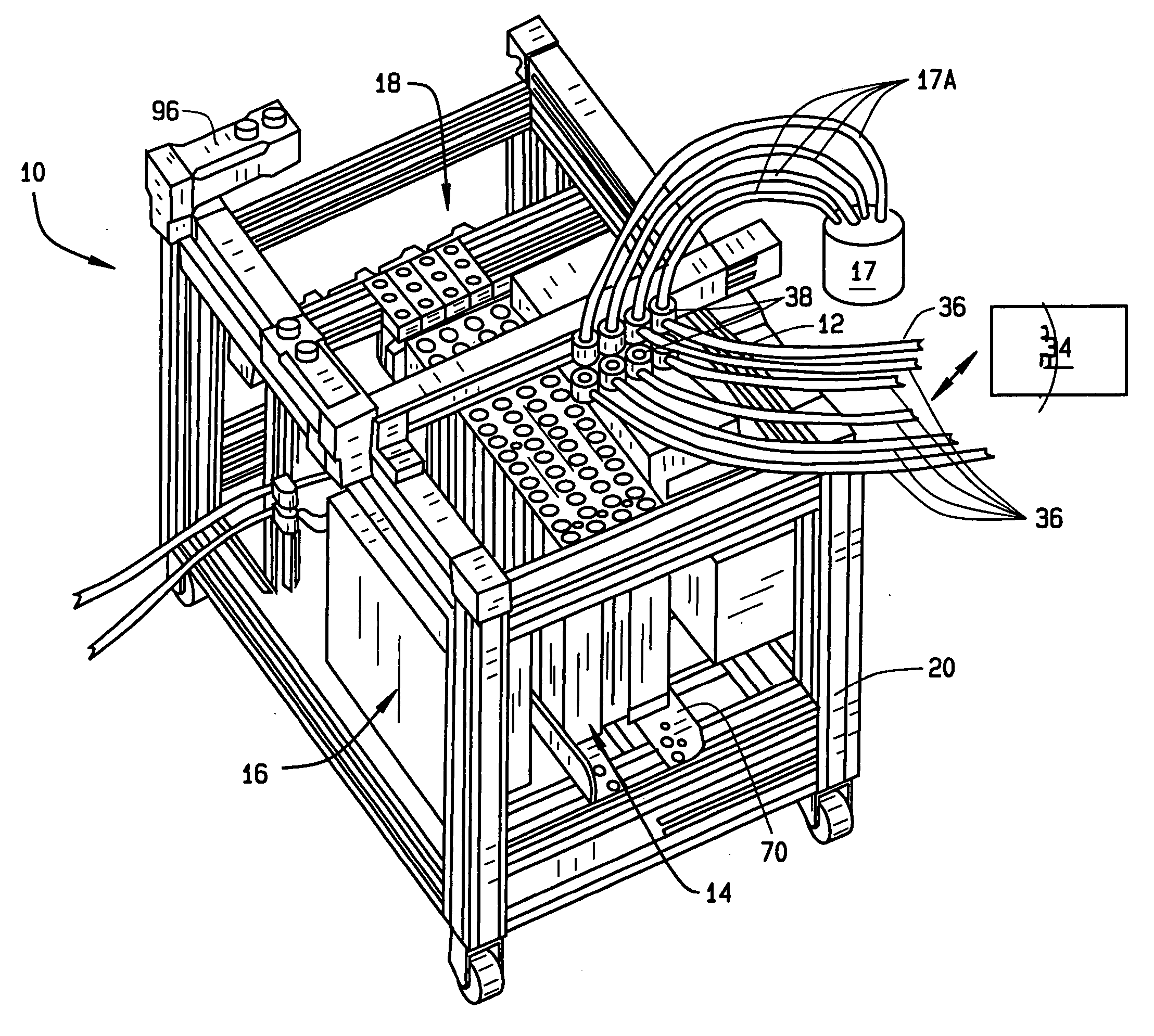
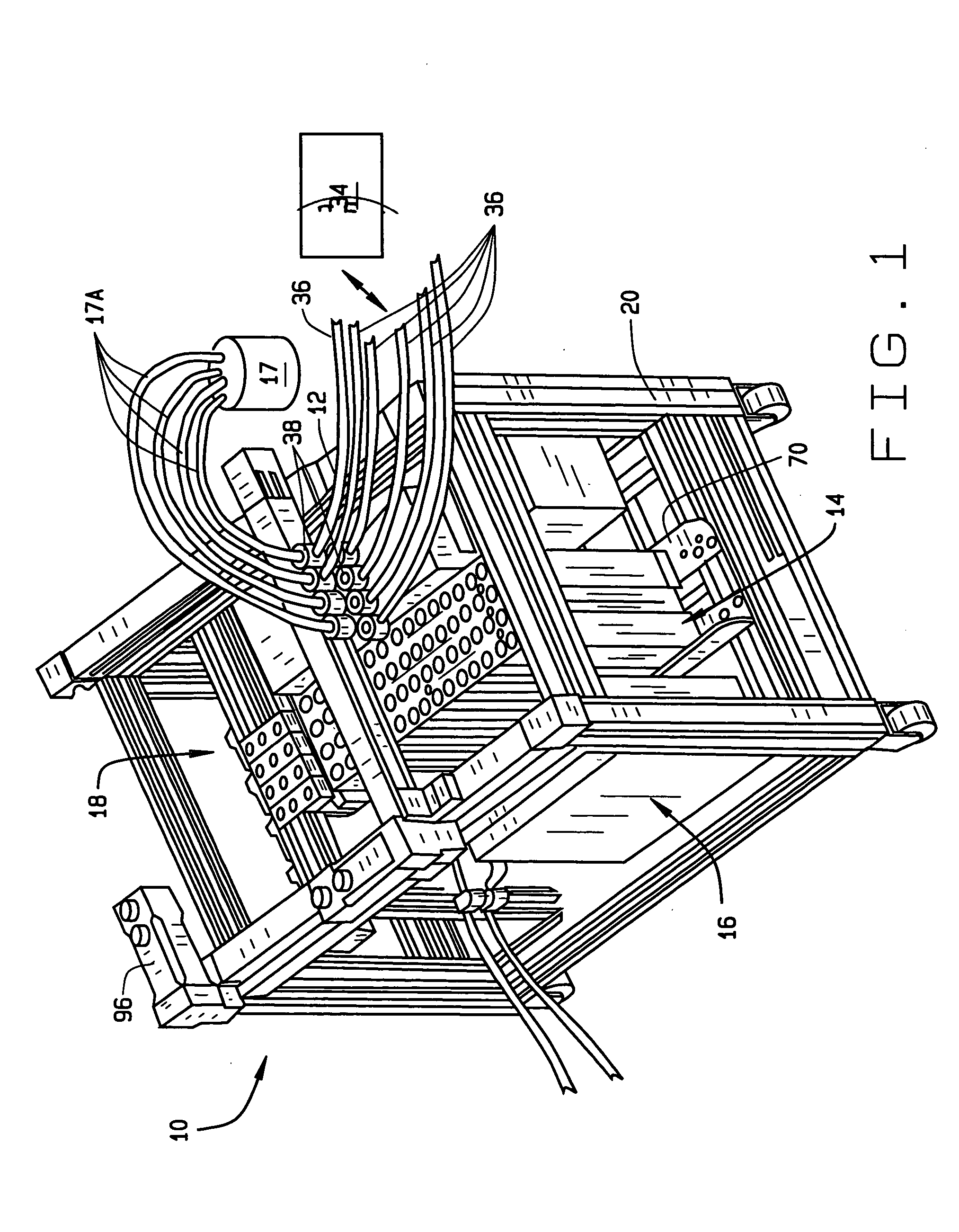
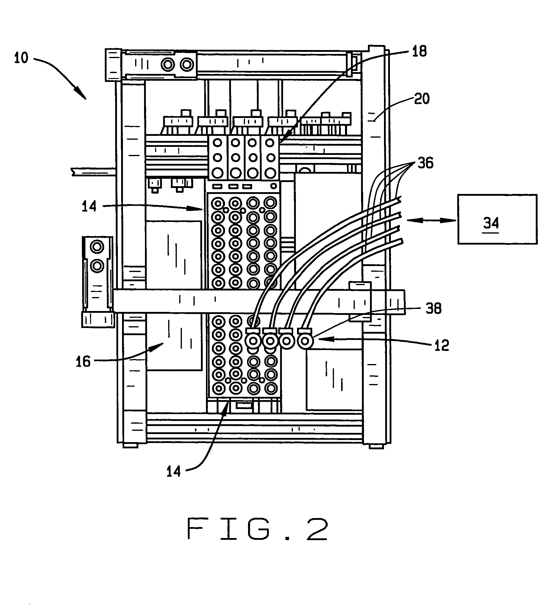
[0029] Referring to the FIG. 1 and 2, a portable fastener delivery system according to the present invention is illustrated and generally indicated by reference numeral 10. The portable fastener delivery system 10 includes an unloading mechanism 12 in communication with a fastener storage device 14. The portable fastener deliver system 10 also includes a control system 16 that causes the unloading mechanism 12 to remove a fastener and a related fastener spacer from the fastener storage device 14. More specifically, the control system selects a desired fastener having a specific configuration from the fastener storage device 14. The desired fastener and related spacer are removed from the fastener storage device 14. The spacer is transported through the unloading mechanism 12 and deposited in a storage receptacle 17 fo...


PUM

PropertyMeasurementUnit
vacuum forceaaaaaaaaaa
diameteraaaaaaaaaa
depthaaaaaaaaaa

Abstract

A system is provided for delivering fasteners to a work station. The system includes at least one fastener storage device than has at least one storage tube. The system additionally includes at least one fastener spacer that is adapted to properly orient at least one fastener stored in the storage tube. The system further includes at least one unloading mechanism that includes at least one extractor catcher. The unloading mechanism is adapted to remove the spacer and the fastener from the storage tube in a single operation.

Description

FIELD OF THE INVENTION [0001] The present invention relates generally to automated fastening equipment and more particularly to a fastener stacking and removal system for use in the automated fastening equipment. BACKGROUND OF THE INVENTION [0002] In the production assembly of aircraft, the majority of substructure such as fuselage frames and longerons, along with wing spars and ribs, are joined to the skin of the aircraft with thousands of fasteners. Further, a plurality of fastener types, along with variations in diameters and grip lengths, are typically used in an aircraft assembly or subassembly. (Generally, a fastener grip length refers to the cumulative thickness of the parts that the fastener holds together). Moreover, a majority of the substructure parts are manually assembled and are not assembled using automated fastening equipment. [0003] Automated fastener delivery systems that automatically deliver fasteners to a workpiece, or a fastening device, have been employed in v...

Claims


Application Information

Patent Timeline
Patent Type & Authority Applications(United States)
IPC IPC(8): B21J15/34B23P19/00
CPCB21J15/32B23P19/003B23P19/002
Inventor BLOCH, DANIEL D.MILLER, WILLIAM P.MCGAHEY, JASON D.
Owner THE BOEING CO
Why Eureka
Try Eureka