Digitizing bar code symbol data

Inactive Publication Date: 2005-01-13
SYMBOL TECH LLC
View PDF9 Cites 17 Cited by
  • Summary
  • Abstract
  • Description
  • Claims
  • Application Information

AI Technical Summary

Benefits of technology

[0006] The invention provides a method and a system for use in digitizing blurred signals representative of bar code symbols by taking into account characteristics specific to bar code symbols, thereby improving the working range and effective resolving power of a bar code scanner by allowing the scanner to decode symbol images acquired at distances or under conditions that cause blurring of the analog signal representing the scanned symbol. Such blurring could result from out-of-focus optics, undersampling, poorly printed symbols, low pass filtering of the analog signal, or other causes. The invention also improves decoding accuracy in the presence of low and high frequency noise.

Problems solved by technology

Such blurring could result from out-of-focus optics, undersampling, poorly printed symbols, low pass filtering of the analog signal, or other causes.

Method used


Image

  • Digitizing bar code symbol data
  • Digitizing bar code symbol data
  • Digitizing bar code symbol data

Examples


Embodiment Construction

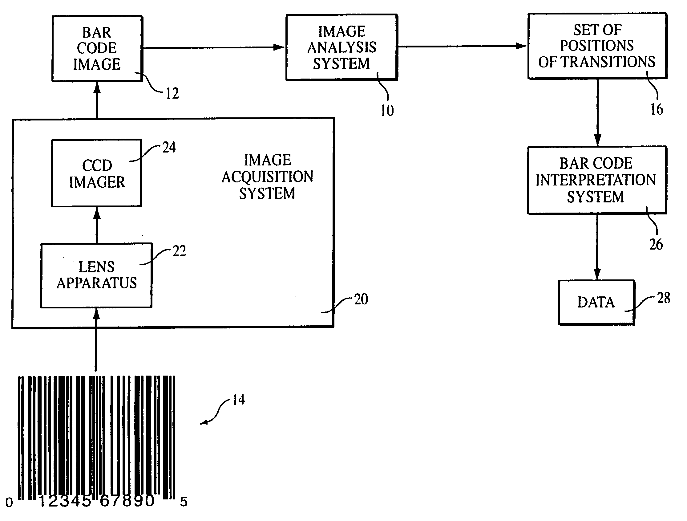
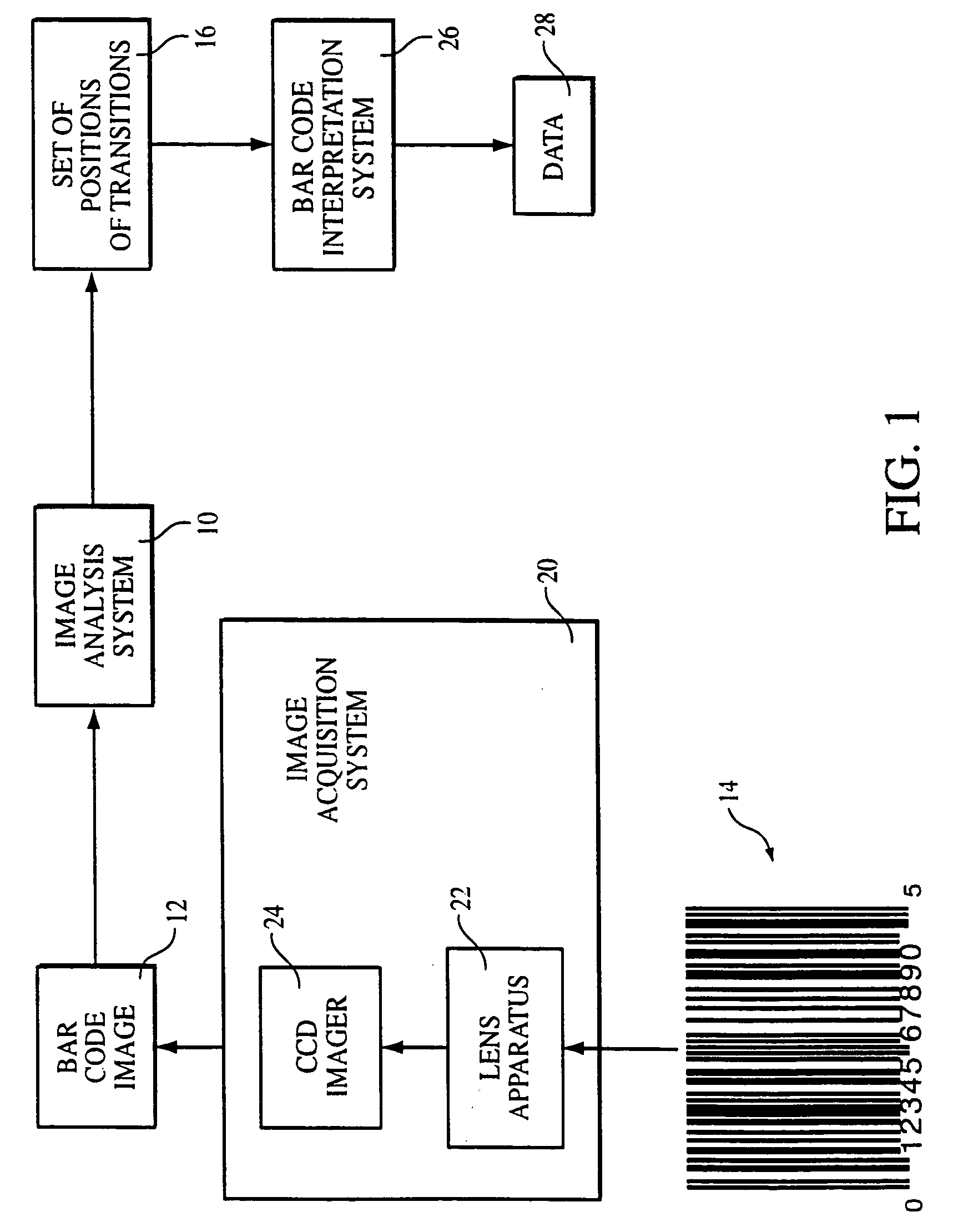
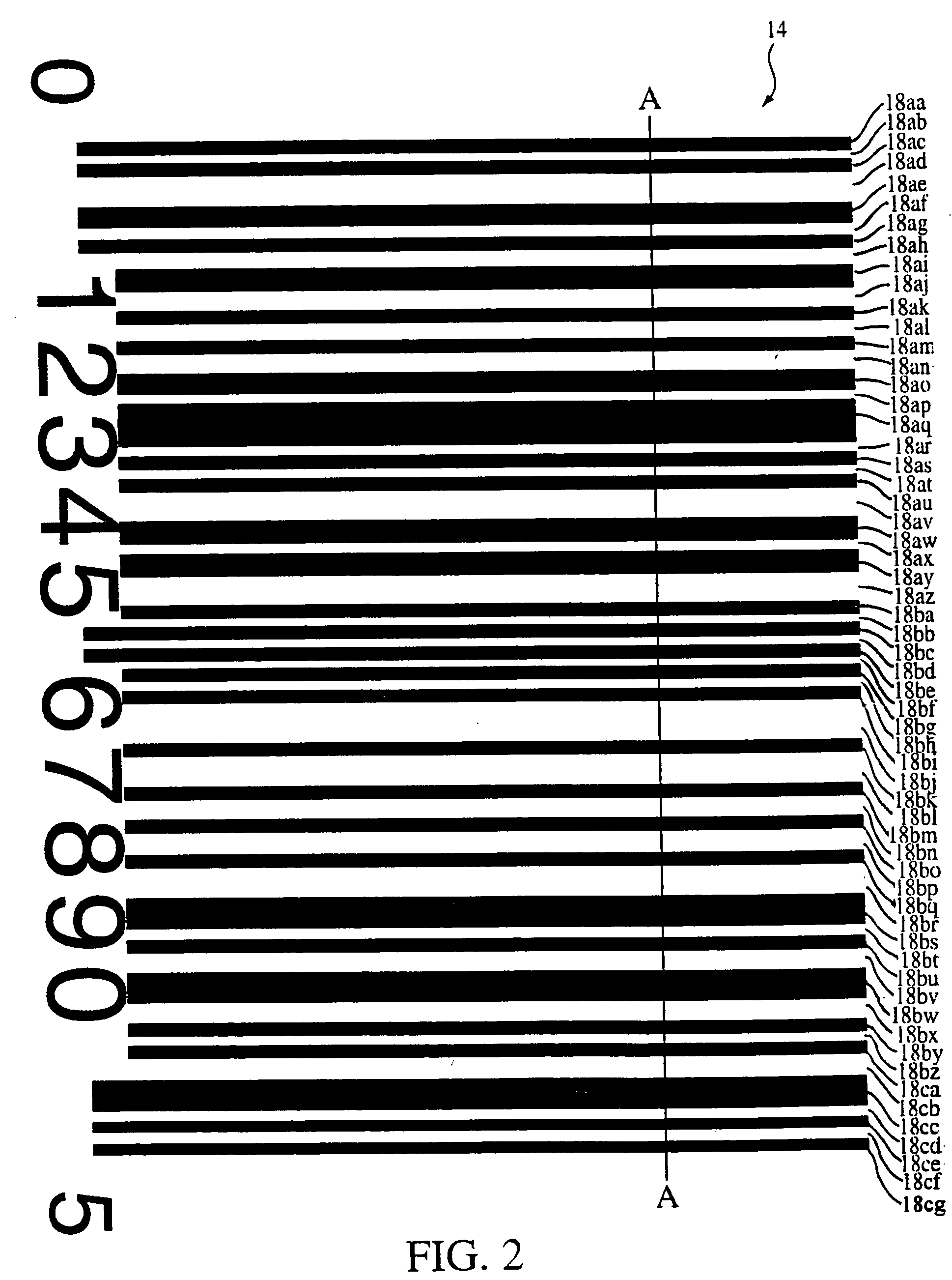
[0028]FIG. 1 illustrates an image analysis system 10 that processes a bar code image 12 representing a bar code symbol (e.g., symbol 14), to determine a set 16 of positions of transitions between portions (e.g., portions 18aa-18cg in FIG. 2) of the bar code symbol. The bar code image is provided by an image acquisition system 20 that may include a lens apparatus 22 and a CCD imager 24, and a bar code interpretation system 26 may derive data 28 (e.g., a serial number) from the set of positions. The image analysis system is able to determine the set of positions even if the bar code image, or signal representing the image, is blurred, by relying on characteristics of blurred bar code images, as described below.

[0029] In a specific embodiment described herein, the positions that are determined are relative in that the positions indicate relationships among the transitions and are not used to determine absolute distances between transitions or absolute widths of portions of the bar cod...


PUM


Abstract

Processing an analog electrical signal containing information representative of reflected light from indicia including regions of different light reflectivity, wherein the analog electrical signal contains edge transitions corresponding to boundaries between adjoining regions of different light reflectivity of the indicia. The edge transitions of at least a part of the analog electrical signal are analyzed to determine a level of blur in that part of the electrical signal. Based on the determined level of blur, one of a plurality of different techniques is selected for processing that part of the electrical signal to produce a digitized electrical signal in which transitions in the digital level of the signal correspond to boundaries between adjoining regions of different light reflectivity of the indicia.

Description

CROSS-REFERENCE TO RELATED APPLICATIONS [0001] This application is a continuation-in-part patent application of U.S. Ser. No. 9 / 981,395, filed Oct. 16, 2001, which is a continuation patent application of U.S. Ser. No. 9 / 096,164, filed Jun. 12, 1998.BACKGROUND OF THE INVENTION [0002] The invention relates to digitizing bar code symbol data. [0003] Bar codes symbols are graphical objects that encode information as alternating dark and light portions, i.e., alternating regions of different light reflectivity, having specific relative widths. Bar code scanners have a wide range of applications, including reading bar code symbols provided on products. From analog electrical signals containing information representative of reflected light from the bar code symbols, the scanners produce digitized electrical signals that are typically fed to computing apparatus for decoding and providing an identification of the product to which the bar code symbol is applied. Examples of bar code symbols a...

Claims


Application Information

Patent Timeline
IPC IPC(8): G06K7/14
CPCG06K7/1452G06K7/14
Inventor HE, DUANFENGJOSEPH, EUGENE
Owner SYMBOL TECH LLC
Why Eureka
Try Eureka