Storage locking apparatus

a technology for locking apparatuses and storage, which is applied in the direction of keyhole guards, mechanical control devices, instruments, etc., can solve the problems of restricting the effective space of the glove box, preventing rattling of the operating handle, and reducing the efficiency of the glove box. , to achieve the effect of ensuring smooth operation, significantly rationalizing invention, and reducing rattling

Inactive Publication Date: 2005-01-13
PIOLAX CO LTD
View PDF12 Cites 6 Cited by
  • Summary
  • Abstract
  • Description
  • Claims
  • Application Information

AI Technical Summary

Benefits of technology

[0013] Therefore, according to the invention described in the first aspect, in view of a relationship in which the operating handle pivoted from an upper side to a lower side is axially supported by an upper end edge of the storage and a portion of the supporting member in correspondence with the operating handle is partitioned with the operating space for inserting the finger, a portion unnecessarily projected to an inner side of the storage as in the prior art is dispensed with and therefore, there is not a concern of constituting a hindrance in inputting in and out small articles and an inner space of the storage can effectively be utilized.
[0014] According to the invention described in the second aspect, in view of a relationship in which the link member and the lever member constituting the lever mechanism are switched between the sliding contact state and the nonsliding contact state, the invention can be applied to embody for a locking apparatus having a key cylinder and for a locking apparatus which is not provided with a key cylinder and therefore, the invention becomes significantly rational. According to the invention described in the third aspect, in view of a relationship in which the second urging member for urging the front end portion of the link member is provided to the side of always urging the front end portion of the link member, rattling of the operating handle can effectively be prevented. According to the invention described in the fourth aspect, in view of a relationship in which the front end portion of the link member, the front end portion of the lever member and the engaging portion of the locking member are arranged successively from an upper side, the apparatus per se can be downsized by thinning the sliding contact portion of the three members.
[0015] According to the invention described in the fifth aspect, in view of a relationship in which the lever member is connected to the eccentric shaft of the key cylinder lock between an axially supported position thereof and the three member sliding contact portion, the invention serves also as a guide in pivoting the lever member and therefore, smooth operation can be guaranteed. According to the invention described in the sixth aspect, in view of a relationship in which the operating claw present between an axially supported position of the operating handle and a side portion thereof is engaged with the connecting hole present on the side opposed to the three members sliding contact portion by interposing the axially supported position of the link member, an angle of operating the operating handle becomes obtuse, an amount of moving the locking member is reduced, a distance between the locking claw and the locking member can be increased and therefore, also an operating force is reduced.

Problems solved by technology

Therefore, although the locking apparatus of the prior art achieves at least an advantage of capable of simply locking and unlocking the glove box, the operating space of putting the finger between the operating handle and the glove door needs to partition in view of a relationship of pivoting the operating handle from the lower side to the upper side and therefore, the glove door is integrally formed with the containing portion in the recessed shape, however, since the containing portion is significantly projected to an inner side of the glove box, there is a concern of constituting a hindrance in putting small articles into and from the glove box, or restricting an effective space of the glove box.

Method used


Image

  • Storage locking apparatus
  • Storage locking apparatus
  • Storage locking apparatus

Examples


Embodiment Construction

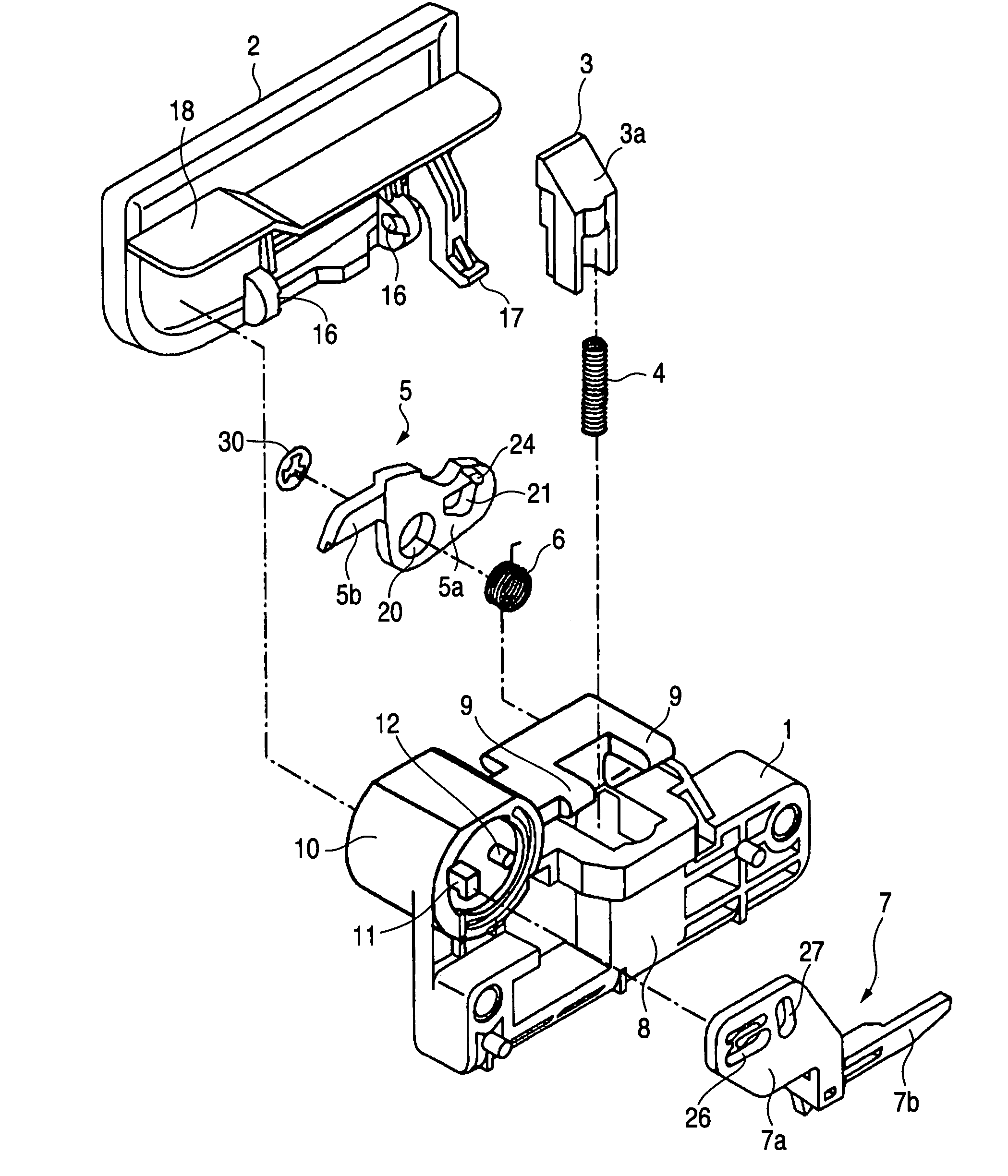
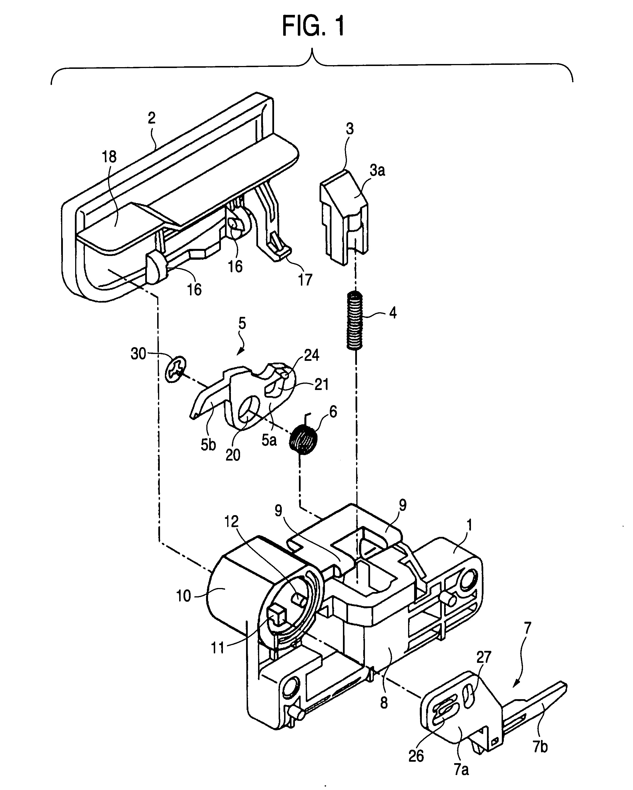
[0030] When a detailed description is given of the invention based on an illustrated preferable embodiment as follows, as shown by FIG. 13, similar to the prior art, also a locking apparatus according to the embodiment has been developed with an object of a glove box B openably and closably attached to an instrument panel P of an automobile, the embodiment is characterized in that an upper end edge of a glove door Ba of the glove box B constituting a storage is provided with an operating handle 2 pivoted from an upper side to a lower side, a portion of the instrument panel P constituting a supporting member is partitioned with an operating space 31 for inserting the finger and the glove box B can be unlocked by operating to pivot the operating handle 2 from the upper side to the lower side by utilizing the operating space 31. Therefore, it is not necessary to provide the operating space 31 for inserting the finger on a side of the glove box B, a portion of the glove box B projected ...


PUM


Abstract

An storage locking apparatus including a case attached to an end edge of the storage, a locking member slidably supported by the case for engaging with and disengaging from the supporting member, a first urging member for always urging the locking member in a direction of the supporting member, an operating handle pivotably supported axially by the case for unlocking the storage by being pivoted from a side of the supporting member to a side of the storage, and lever mechanisms for sliding the locking member against the first urging member by pivoting the operating handle in which the supporting member dispenses with a containing portion in a recessed shape as in a prior art by providing an operating space between the supporting member and the operating handle.

Description

BACKGROUND OF THE INVENTION [0001] 1. Field of the Invention [0002] The present invention relates to an improvement in an storage locking apparatus such as, for example, glove box openably and closably attached to an instrument panel of an automobile. [0003] 2. Description of the Related Art [0004] A locking apparatus of this kind of a prior art is constructed by a constitution in which whereas a central portion of a glove box door is integrally formed with a containing portion in a recessed shape, a locking member engaging with and disengaging from a striker provided on a side of an instrument panel is liftably supported at inside of the containing portion in the recessed shape and the locking member is elastically urged to an upper side by urging spring pressure, an operating handle is pivotably supported axially by two side walls of the containing portion in the recessed shape and a front end side of the operating handle is continuously provided with an engaging arm for engaging ...

Claims


Application Information

Patent Timeline
Patent Type & Authority Applications(United States)
IPC IPC(8): E05B65/12E05B65/20
CPCE05B85/18E05B83/30Y10S292/27Y10S292/31Y10S292/63Y10T70/5761Y10T292/57Y10T292/0974Y10T70/5805Y10T70/5496Y10T70/5416Y10T292/0886
Inventor YAMADA, SATOSHISHIMIZU, TOSHIHIRO
Owner PIOLAX CO LTD
Why Eureka
Try Eureka