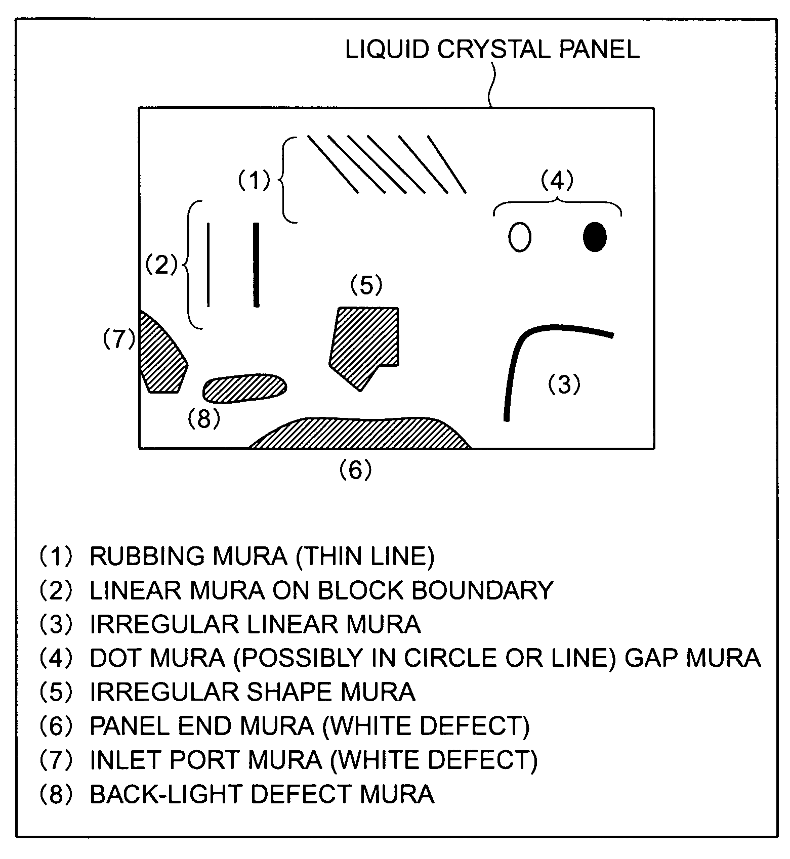
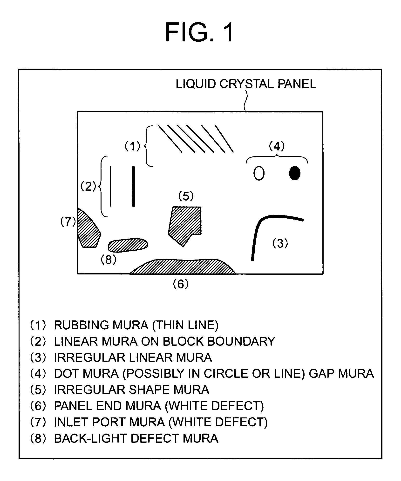
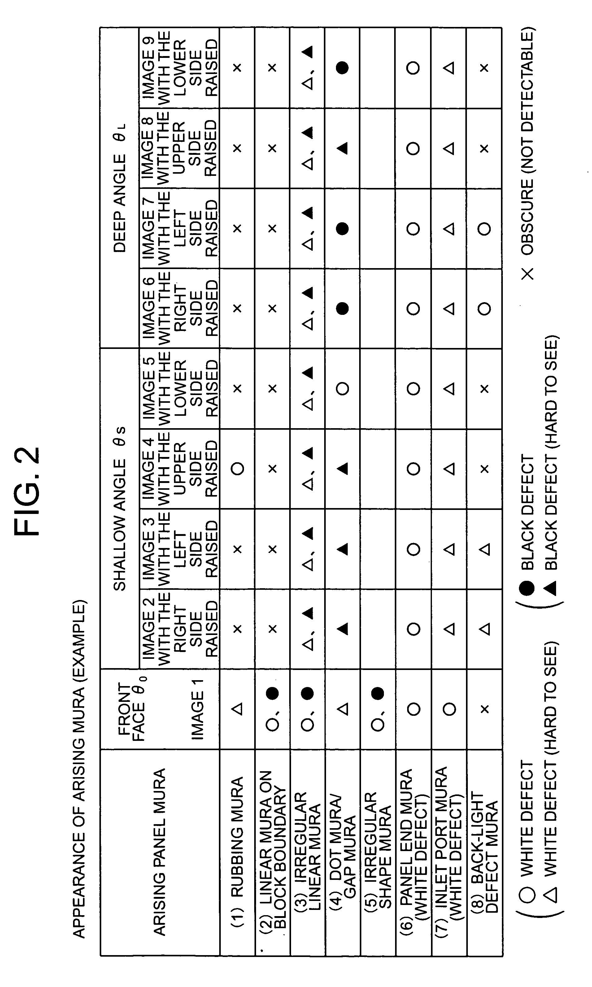
Method for sorting ununiformity of liquid crystal display panel sorting apparatus, and information recorded medium with recorded program for executing this sorting

Inactive Publication Date: 2005-01-13
JAPAN SCI & TECH CORP
View PDF3 Cites 44 Cited by
  • Summary
  • Abstract
  • Description
  • Claims
  • Application Information

AI Technical Summary

Benefits of technology

[0006] In this invention, detection of panel MURA is made by detecting a structural panel MURA without setting up the complicate parameters by employing not a single image in one dire

Problems solved by technology

The problem with this method is a complicate process for detecting the MURA because there are various kinds of parameter settings and the fine setting of threshold values must be performed.
Also, if the kind of product is changed, excess operations for changing the housekeeping may be needed.
However, for the MURA dependent on the panel structure such as the

Method used


Image

  • Method for sorting ununiformity of liquid crystal display panel sorting apparatus, and information recorded medium with recorded program for executing this sorting
  • Method for sorting ununiformity of liquid crystal display panel sorting apparatus, and information recorded medium with recorded program for executing this sorting
  • Method for sorting ununiformity of liquid crystal display panel sorting apparatus, and information recorded medium with recorded program for executing this sorting

Examples


example 2

[0054] In the example of FIG. 4, the MURA detection classification process is implemented on the personal computer or workstation using a software program. In this example, the process (steps S10, S30 to S40, S11, S21 to S41, . . .) for the MURA area detection in the processing algorithm is easily provided by hardware. This MURA area detecting process is performed in parallel and fast by employing DSP (Digital Signal Processor) or a programmable gate array such as FPGA (Field Programmable Gate Array).

[0055]FIG. 10 is a concept view showing a classification processing device for the liquid crystal display panel MURA in which the programmable gate array is used for the MURA detecting process of the invention. In FIG. 10, 1 denotes a classification processing device for the liquid crystal display panel MURA that is constituted of a computer, 2 denotes a liquid crystal display panel photographing device, 3 denotes a control signal from the classification processing device 1 for the pan...

example 3

[0060] Plural groups of images of the liquid crystal display panel photographed from different angles of visibility are taken in, and a program for performing the procedure of FIG. 4 to classify and identify the liquid crystal display panel MURA is created, and recorded on an information recording medium such as CD-ROM. For example, the program recorded on the information recording medium is read by a reader of the input unit 13 in the computer of FIG. 10, and installed or downloaded into the memory 11M to enable the computer to perform the processing procedure of FIG. 4.


PUM


Abstract

The present invention relates to a process for classifying the panel MURA in the module inspection of a liquid crystal display panel.
The invention includes a MURA area logical operation process (S5) of photographing the liquid crystal display panel from different angles of visibility, performing an image processing for detecting a MURA area for a group of images taken and then performing an image logical operation process, an upper-level classification process (S6) of classifying the shape of MURA, and a lower-level classification process of classifying the panel MURA by combining an upper-level classification with other parameters. With this invention, the panel MURA is correctly detected without setting up the complicate parameters. This invention contributes to labor saving at the final inspection step for manufacturing and leads to quality assurance and higher reliability of the liquid crystal display panel in the liquid crystal display panel manufacturing field.

Description

TECHNICAL FIELD [0001] The present invention relates to a classification process of panel MURA in a module inspection for a liquid crystal display panel, and more particularly to a MURA classification process making use of plural panel photograph images that are photographed from different angles of visibility. BACKGROUND ART [0002] Automated MURA inspection for the liquid crystal display panel has been attempted in various parts of the industry. In this case, it is common practice that one sheet of image photographed from the front face of panel, namely, one sheet of image that may possibly have MURA is processed through the image processing techniques to detect any MURA present on the image. In this specification, the term imperfection that can be represented by blemish, blotch or unevenness is referred to as MURA, a transliterated Japanese word. [0003] Also, to optimize the detection conditions of MURA, various kinds of parameters for detection had various thresholds different a ...

Claims


Application Information

Patent Timeline
IPC IPC(8): G01M11/00G01N21/95G02F1/13G06T7/00G09F9/00G09F9/35
CPCG02F1/1309G06T7/0065G06T7/0004G06T7/55
Inventor OYAMA, YOSHIFUMIOOKUMA, YOSHINOBU
Owner JAPAN SCI & TECH CORP
Why Eureka
Try Eureka