Lens driving mechanism and image capture apparatus

a driving mechanism and lens technology, applied in the direction of mountings, optics, instruments, etc., can solve the problems of difficult shortening of lead screws, parts damage and trouble in cameras, nuts attempting to move beyond, etc., and achieve the effect of shortening the length of the output axis

Inactive Publication Date: 2005-01-13
SONY CORP
View PDF5 Cites 13 Cited by
  • Summary
  • Abstract
  • Description
  • Claims
  • Application Information

AI Technical Summary

Benefits of technology

[0016] In present invention having the above-mentioned configuration, the idle rotation section is provided on only one end of the output axis to which the nut is screwed. Accordingly, as compared with a case in which the idle rotation sections are placed both ends of the output axis, the present invention makes it possible to shorten the length of the output axis.

Problems solved by technology

However, in such conventional techniques, if a control error or the like occurs and cause parts that is to be driven (a lens frame) to reach an end of driving limit, the nut tries to move beyond a movement limit.
In consequence, biting of a screw thread of the nut may occur, and become a cause of parts damage and troubles in cameras.
However, if such an idle rotation section is provided, it is very difficult to shorten the lead screw.
Further, since the forcing element is placed on the base side and tip side of the guiding axis, it is difficult to shorten the guiding axis and a tip cover of the guiding axis.
In consequence, there is drawback such that those factors may become hindrance to further reduction in size of the lens barrel, which is configured as a unit, and reduction in thickness of storage space for the collapsible barrel.

Method used


Image

  • Lens driving mechanism and image capture apparatus
  • Lens driving mechanism and image capture apparatus
  • Lens driving mechanism and image capture apparatus

Examples


first embodiment

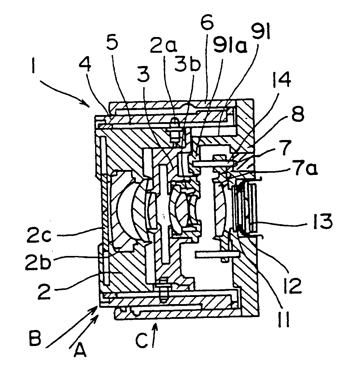
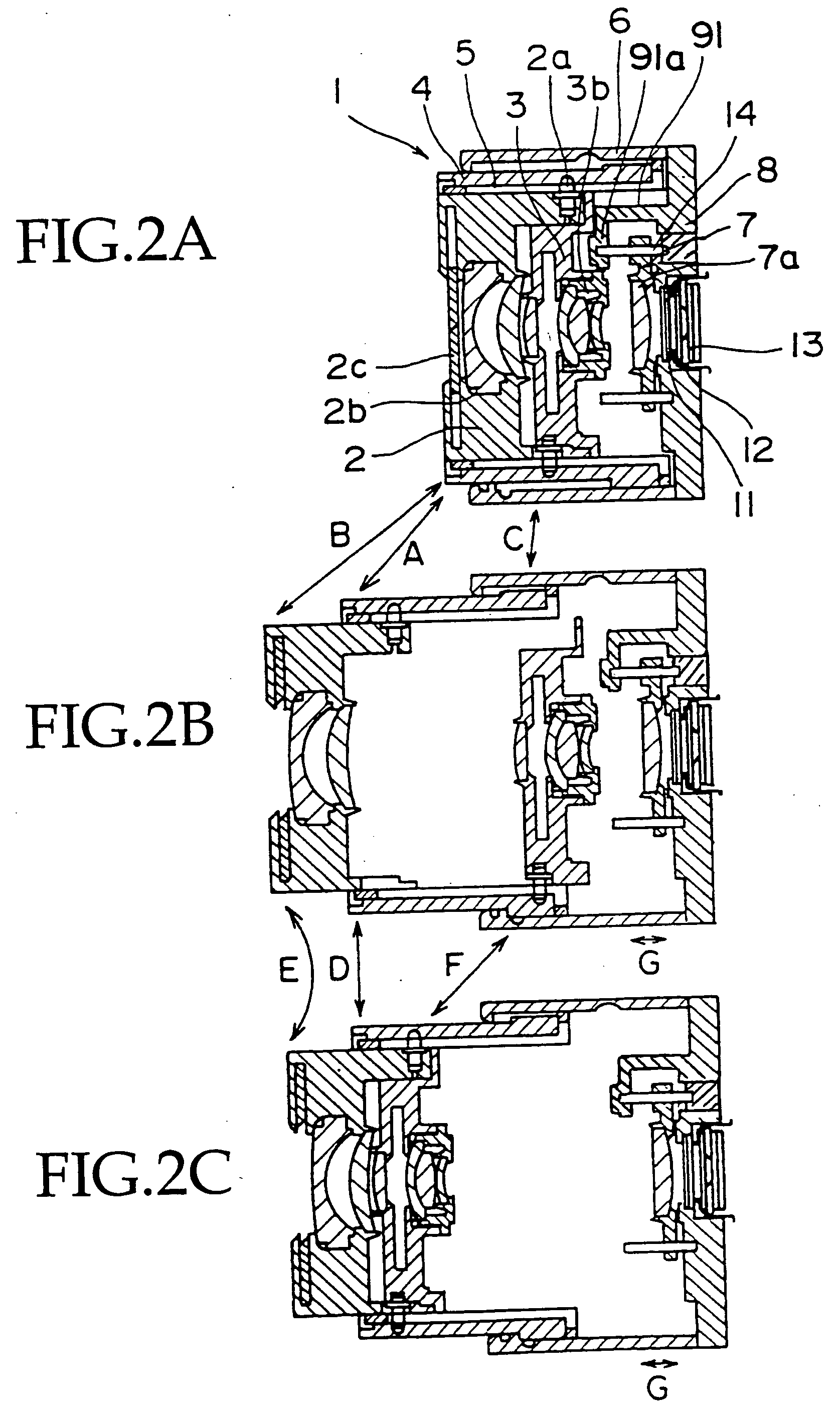
[0049] In the above-mentioned first embodiment, it is enough to place the idle rotation section 15c on only one side of the ends of the lead screw 15a. Thus, as compared with the mechanism in the related art in which the idle rotation sections are placed on both ends of the lead screw 15a, the length of the lead screw 15a maybe shortened, which allow the entire lens barrel to be thinner.

[0050] Further, the idle rotation section 15c is placed at the end of the imaging device side (the right side of FIG. 4) in the lead screw 15a, and the arm 17 and the spring 9 are placed on the photographing device side with respect to the nut 16. Accordingly, even if the nut 16 is not moved since the power source to the stepping motor 15 is turned off when the lens L is collapsed (refer to FIGS. 1A, 2A), the third group frame 7 is allow to be pushed into the imaging device side, thereby attaining the thinner size at the time of storage space of the lens L.

[0051] A second embodiment of the lens driv...

second embodiment

[0056] As mentioned above, it is enough to place the idle rotation section 15c on one side of the ends of the lead screw 15a. Thus, as compared with the conventional mechanism in which the idle rotation sections are placed on both ends of the lead screw 15a, the length of the lead screw 15a may be shortened, which allows the entire lens barrel to be thinner. Further, in the second embodiment, the spring 9 is placed around the lead screw 15a. Thus, a direction of the force to be applied from the nut 16 to the arm 17 and a direction of force with the spring 9 allow to be adjusted coaxially, which enables the arm 17 to move forward and backward smoothly.

[0057] A third embodiment of the lens driving mechanism according to the present invention will be described below. FIG. 6 is a partially sectional view explaining the third embodiment. The lens driving mechanism according to this embodiment is characterized in that the idle rotation section 15c of the nut 16 is placed on only the subje...


PUM


Abstract

This prevents biting and miniaturizes an entire mechanism. There is provided a lens driver including: a driver having a frame that holds a lens and a bearing for receiving a guiding axis to move the lens in an optical axis direction, a lead screw in which a screw to which a nut is screwed is formed, and a stepping motor for rotating the lead screw; an arm extended from the frame, in such a way a tip being next to the nut, and moving the frame by movement of the nut; a spring for pushing an arm tip towards the nut; and an idle rotation section placed on only side where the arm is placed for the nut at a lead screw end of the driver, and has an axis diameter disabling the nut to be screwed. Also there is provided an image capture apparatus having the lens driver.

Description

CROSS REFERENCES TO RELATED APPLICATIONS [0001] The present invention claims priority to its priority document No. 2003-140027 filed in the Japanese Patent Office on May 19, 2003, the entire contents of which being incorporated by reference herein. BACKGROUND OF THE INVENTION [0002] 1. Field of the Invention [0003] The present invention relates to a lens driving mechanism and an image capture apparatus that move a lens, which carries out a focusing operation and the like, in an optical axis direction, and more specifically a lens driving mechanism and an image capture apparatus that have a clearance in the driving mechanism if an error occurs in a movement control of a lens. [0004] 2. Description of Related Art [0005] In recent years, improvement of portability and advancement of convenience are demanded for the image capture apparatuses, such as a digital still camera, a digital video camera and the like. Furthermore, reduction of the total apparatus size and sizes of an optical sy...

Claims


Application Information

Patent Timeline
Patent Type & Authority Applications(United States)
IPC IPC(8): G02B7/04G02B7/10
CPCG02B7/10G02B7/021
Inventor MAKII, TATSUOAOKI, NOBUAKIOGIYAMA, HIROTO
Owner SONY CORP
Why Eureka
Try Eureka