
Led-based flashlight

Inactive Publication Date: 2005-01-13
OPTICS 1
View PDF8 Cites 25 Cited by
  • Summary
  • Abstract
  • Description
  • Claims
  • Application Information

AI Technical Summary

Benefits of technology

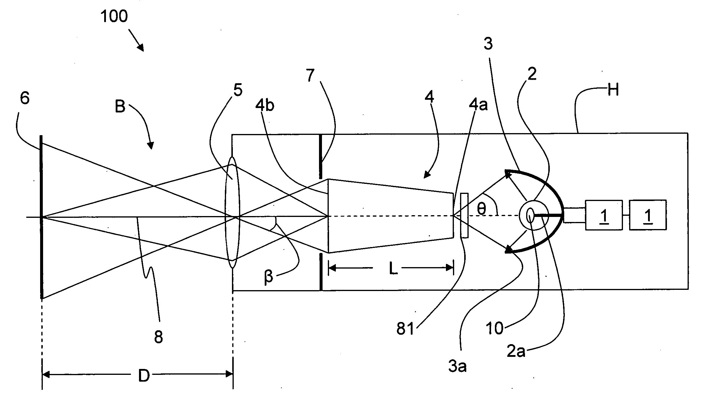
[0009] A first aspect of the invention is a flashlight for uniformly illuminating an object to be viewed. The flashlight includes a light pipe having an input face and an output face, and an array of one or more light-emitting diodes (LEDs) optically coupled to the input face of the light pipe. The flashlight also includes an imaging lens arranged adjacent the light pipe output face and at an output end of the flashlight. The imaging lens is adjustable so that a relatively uniform distribution of light is formed at a selectable distance from t

Problems solved by technology

A significant problem with the current flashlight technology is that the crude image (usually a circular spot) varies significantly in its intensity.
While some flashlights permit the user to vary or adjust the size of the pattern, it is generally highly non-uniform in intensity over the spot.
Another problem is that the light spills out to a wide area outside of the intended spot area.
Another problem is that the crude image cast by a conventional flashlight makes it difficult in many circumstances to clearly see the object of interest.
Another problem is that the illuminated area of prior art flashlights tends to be unattractive and unfamiliar.
Unfortunately, conventional flashlights do not provide such illumination.

Method used


Image

  • Led-based flashlight
  • Led-based flashlight
  • Led-based flashlight

Examples


Embodiment Construction

[0022] For the purposes of explanation, specific embodiments are set forth to provide a thorough understanding of the present invention. However, it will be understood by one skilled in the art, from reading the disclosure, that the invention may be practiced without these details. Moreover, well-known elements, process steps, and the like, and including, but not limited to, optical components, electronic circuitry components and connections, are not set forth in detail in order to avoid obscuring the disclosed system.

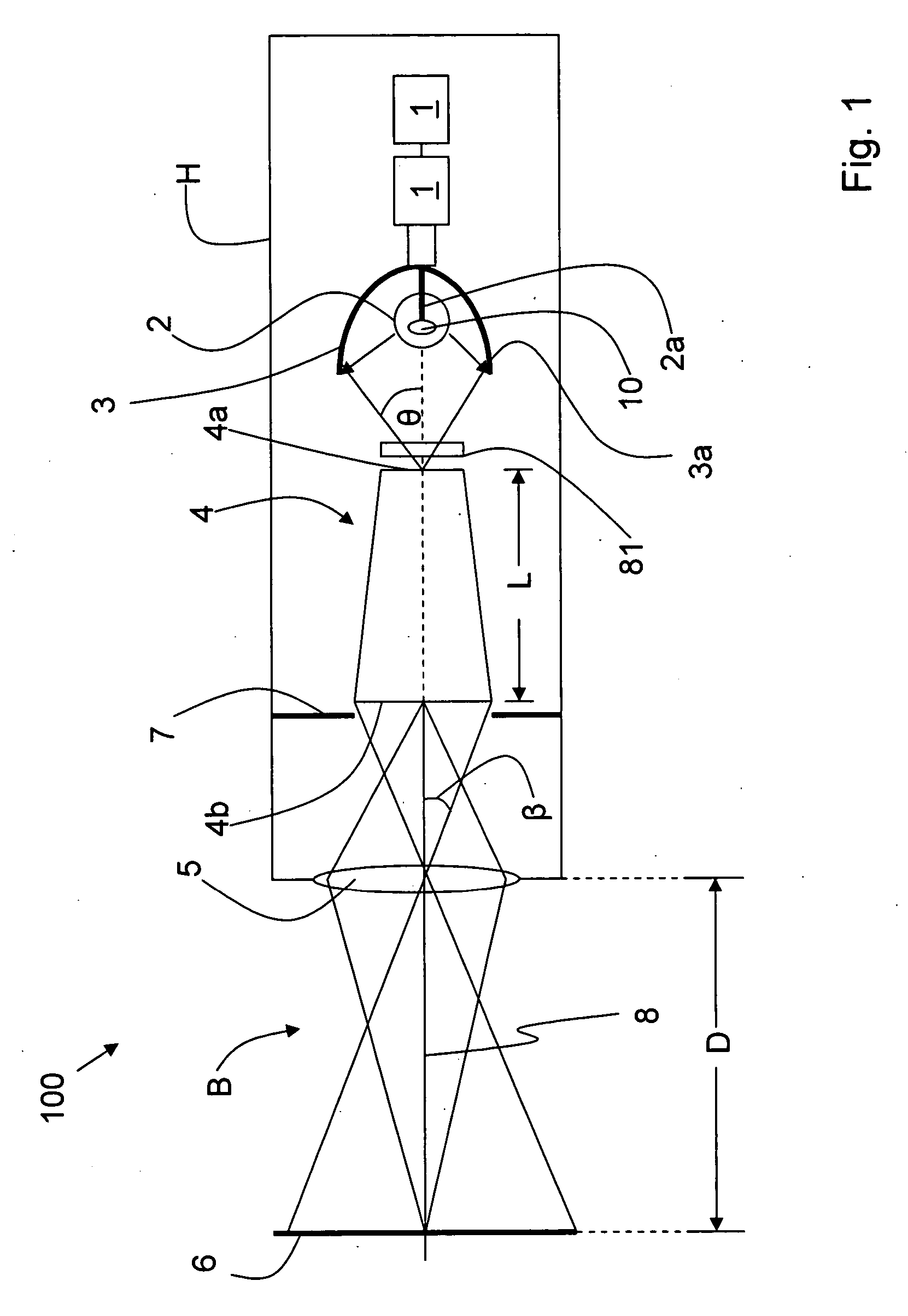
[0023] The preferred example embodiment of the flashlight invention 100 is shown in FIG. 1. Flashlight 100 includes a housing H which serves to enclose and / or support and protect the various elements making up the flashlight as described below. Two ordinary flashlight batteries 1 are shown in flashlight 100 of FIG. 1, but any number of batteries (i.e., one or more), or types of batteries, or any applicable power source will work as a power source for a conventional or...


PUM


Abstract

A flashlight that utilizes an array of one or more light-emitting diodes (LEDs) as a light source, and a light pipe as a light homogenizer to generate a light beam capable of forming a uniformized light distribution at a given distance from the flashlight is disclosed. The LEDs may be all the same color, or some or all may be different colors. A switch, coupled to switching electronics coupled to the LED array, is used to change the state of the LED array to create a variety of different types of light beams, each of which provides relatively uniform and bright illumination at a given distance from the flashlight, wherein the given distance is selectable by adjusting an adjustable imaging lens.

Description

CROSS-REFERENCE TO RELATED APPLICATIONS [0001] This application is a continuation-in-part of U.S. patent application No. 10 / 068,366, now U.S. Pat. No. ______, filed on Feb. 5, 2002, which in turn claims priority from U.S. Provisional Application No. 60 / 266,589, filed Feb. 6, 2001.BACKGROUND INFORMATION [0002] 1. Field of the Invention [0003] This invention relates to flashlights that utilize light-emitting diodes (LEDs) as a light source. [0004] 2. Description of the Related Art [0005] The flashlight was invented in 1898 by Conrad Hubert who turned a metal tube, a light bulb and a battery into the world's first flashlight. Little has changed in flashlight technology since then. Today's flashlight technology is based on locating a tungsten lamp or bulb at the focus of a parabolic reflector and simply imaging the filament out into object space. The reflector may be of other shapes and may be faceted or otherwise modified. At a somewhat distant wall (such as at a distance of 3-6 feet f...

Claims


Application Information

Patent Timeline
IPC IPC(8): F21L4/00F21L4/02F21V5/00F21V5/04F21V7/00F21V9/40F21V11/08F21V14/06G02B27/09G03B21/14G03B21/22G03B29/00
CPCF21L4/00F21V2200/17F21V5/002F21V5/04F21V9/10F21V11/08F21V14/065F21Y2101/02G02B27/0961G02B27/0994G03B21/14G03B21/2013G03B21/2033G03B21/208F21V2200/13F21L4/027F21Y2115/10F21V9/40
Inventor FISCHER, ROBERT E.MOELLER, GREGPRINCE, SIMON
Owner OPTICS 1
Learn More