Multi-purpose non-volatile memory card

Inactive Publication Date: 2005-01-13
SANDISK TECH LLC
View PDF42 Cites 105 Cited by
  • Summary
  • Abstract
  • Description
  • Claims
  • Application Information

AI Technical Summary

Benefits of technology

[0011] The various aspects of the present invention can be implemented as a memory card that is removably insertable into a mating socket of host systems. More specifically, a particular embodiment of the present invention is as an integrated circuit card where user data can be

Problems solved by technology

The problem occurs most pronouncedly between two sets of adjacent cells that have been programmed at different times. One set of cells is programmed to add a level of charge to their floating gates that corresponds to one set of data.
Another potentially adverse effect of increasing the number of programming states of the individual memory cells is a reduction of the life

Method used


Image

  • Multi-purpose non-volatile memory card
  • Multi-purpose non-volatile memory card
  • Multi-purpose non-volatile memory card

Examples


Embodiment Construction

[0026] Example Non-Volatile Memory System

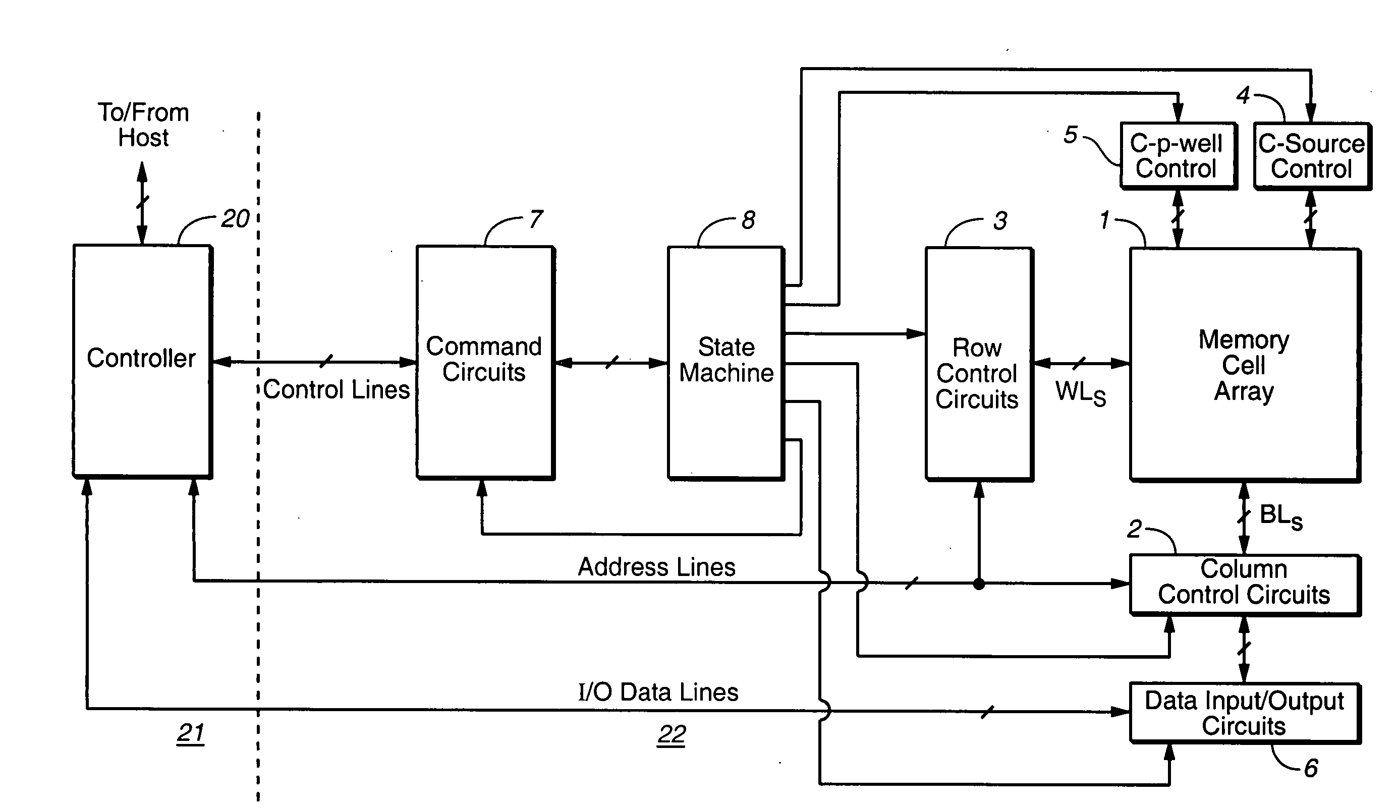
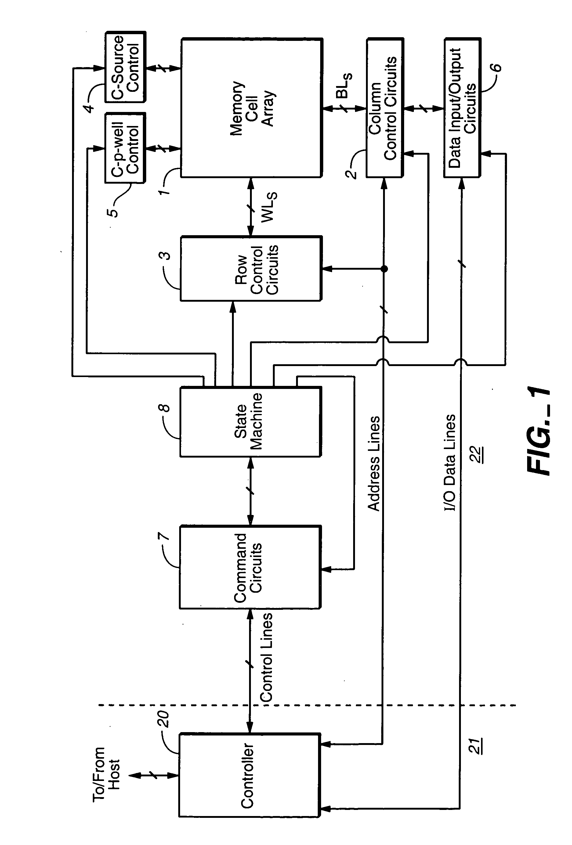
[0027] With reference to FIGS. 1-7, a specific non-volatile memory system is described in which the various aspects of the present invention are implemented, in order to provide specific examples. FIG. 1 is a block diagram of a flash memory system. Memory cell array 1 including a plurality of memory cells M arranged in a matrix is controlled by a column control circuit 2, a row control circuit 3, a c-source control circuit 4 and a c-p-well control circuit 5. The column control circuit 2 is connected to bit lines (BL) of the memory cell array 1 for reading data stored in the memory cells (M), for determining a state of the memory cells (M) during a program operation, and for controlling potential levels of the bit lines (BL) to promote the programming or to inhibit the programming. The row control circuit 3 is connected to word lines (WL) to select one of the word lines (WL), to apply read voltages, to apply a program voltages combined with t...


PUM


Abstract

A flash non-volatile memory system that normally operates its memory cells in multiple storage states is provided with the ability to operate some selected or all of its memory cell blocks in two states instead. The two states are selected to be the furthest separated of the multiple states, thereby providing an increased margin during two state operation. This allows faster programming and a longer operational life of the memory cells being operated in two states when it is more desirable to have these advantages than the increased density of data storage that multi-state operation provides. An exemplary embodiment is as a memory card where the user can choice between two state and multi-state operation.

Description

[0001] The present application is a Continuation in Part of U.S. patent application Ser. No. 10 / 818,926, filed Apr. 5, 2004, which is a Continuation of U.S. patent application Ser. No. 10 / 229,258, filed Aug. 26, 2002, now U.S. Pat. No. 6,717,847, which is in turn a Continuation of U.S. patent application Ser. No. 09 / 956,340, filed Sep. 17, 2001, now U.S. Pat. No. 6,456,528, all of which are hereby incorporated by reference herein.FIELD OF THE INVENTION [0002] This invention relates generally to a non-volatile memory and its operation, and, more specifically, to techniques for selectively operating a multi-state memory in a lesser number of states than it is capable of operating. BACKGROUND OF THE INVENTION [0003] The principles of the present invention have application to various types of non-volatile memories, those currently existing and those contemplated to use new technology being developed. Implementations of the present invention, however, are described with respect to a flas...

Claims


Application Information

Patent Timeline
IPC IPC(8): G11C11/56G11C16/04G11C16/12
CPCG11C11/56G11C11/5621G11C2211/5641G11C16/0483G11C16/12G11C11/5628G11C16/00
Inventor BARZILAI, RONELHAMIAS, REUVEN
Owner SANDISK TECH LLC
Why Eureka
Try Eureka