Low shear impeller

a low shear impeller and impeller technology, applied in the field of low shear impellers, can solve the problem of not being able to insert through the restriction, and achieve the effects of low shear impeller structure, improved mixing efficiency, and improved mixing efficiency

Active Publication Date: 2005-01-13
PHILADELPHIA GEAR
View PDF9 Cites 45 Cited by
  • Summary
  • Abstract
  • Description
  • Claims
  • Application Information

AI Technical Summary

Benefits of technology

[0015] Accordingly, an efficient mixing method and apparatus is provided with aspects that produce a good top to bottom axial flow of product and reduces the tendency of a radially protruding and axially extending impeller structure to promote stratification of the batch. The result is a more full and uniform dispersion of phases through the entire mixing vessel, i.e., improved mixing efficiency, in a low shear impeller structure. This and other advantageous results are obtained from structuring the device so as to add an axial component of flow.

Problems solved by technology

It is not possible to insert through that restriction an impeller with a larger diameter than the opening.

Method used


Image

  • Low shear impeller
  • Low shear impeller
  • Low shear impeller

Examples


Embodiment Construction

[0029] This detailed description refers to the embodiments shown in the respective figures and insofar as terms respecting orientations are found in the description (such as vertical, horizontal, above, below, etc.), such terms are intended to refer to the drawing under discussion and do not limit the orientation of the invention. For example, a vertical impeller shaft rotation axis is generally shown throughout the drawings, but it is likewise possible that other orientations could be used where appropriate. Throughout the respective drawing views, the same reference numbers are used where possible to refer to the same or functionally similar elements.

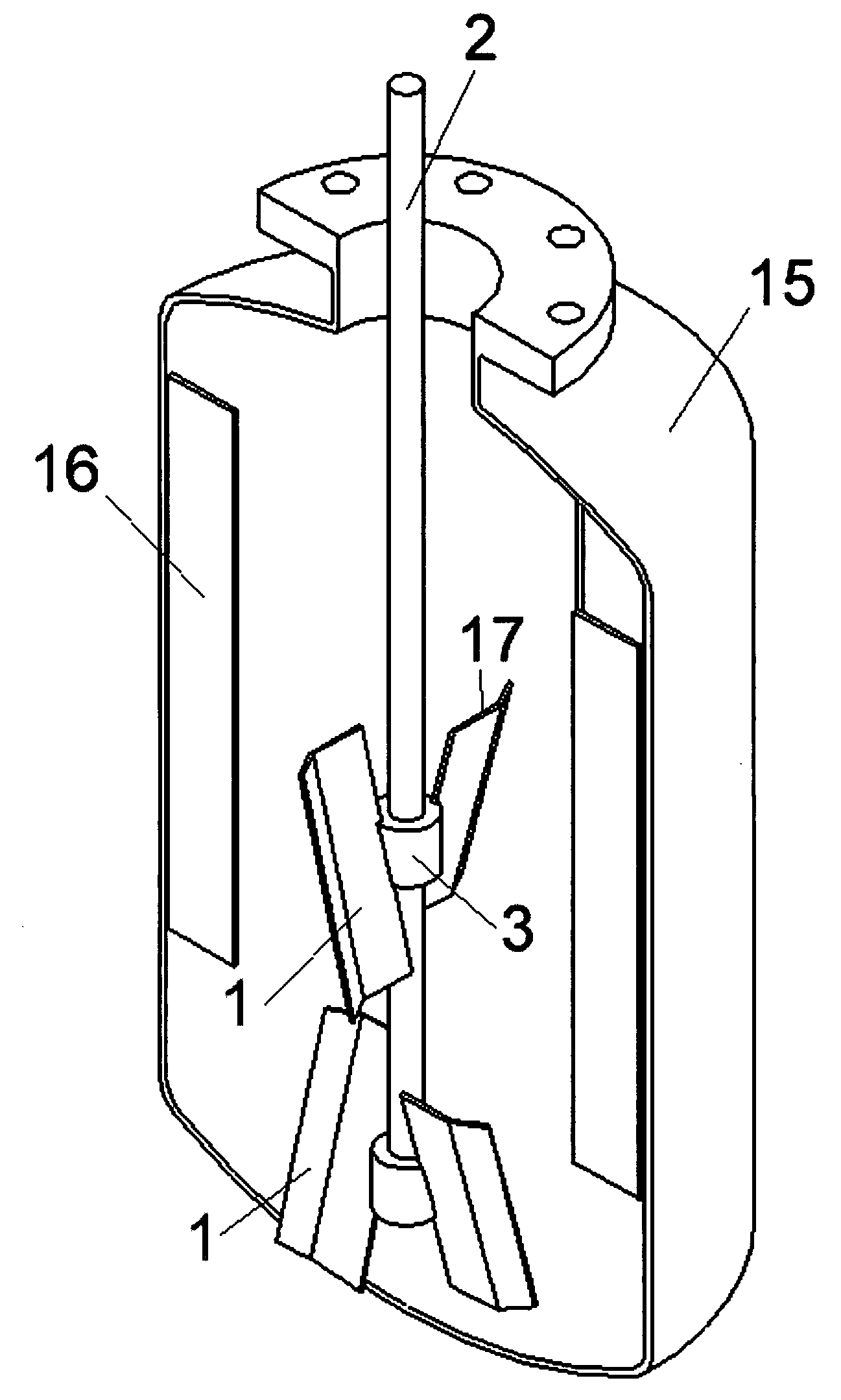
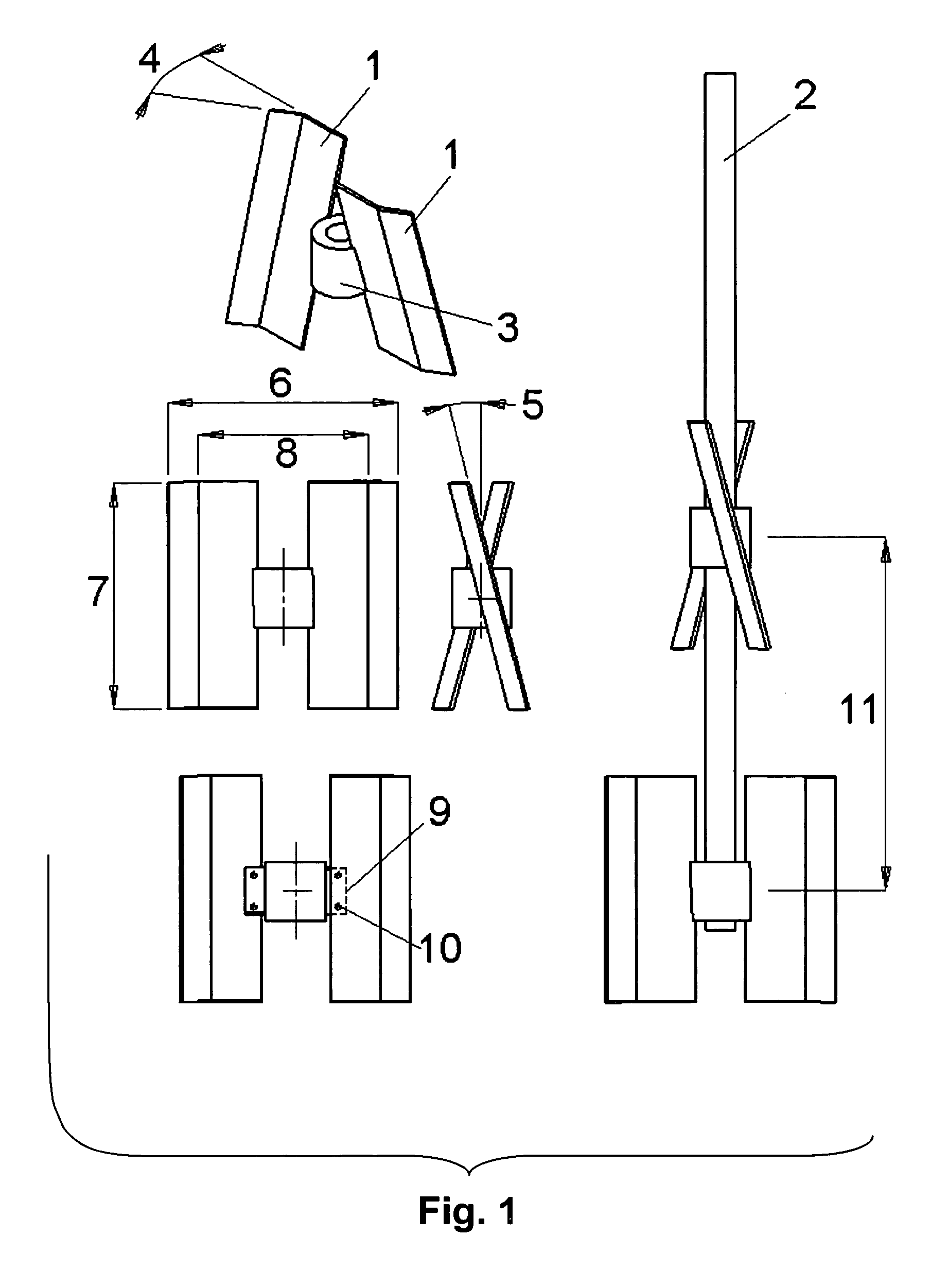
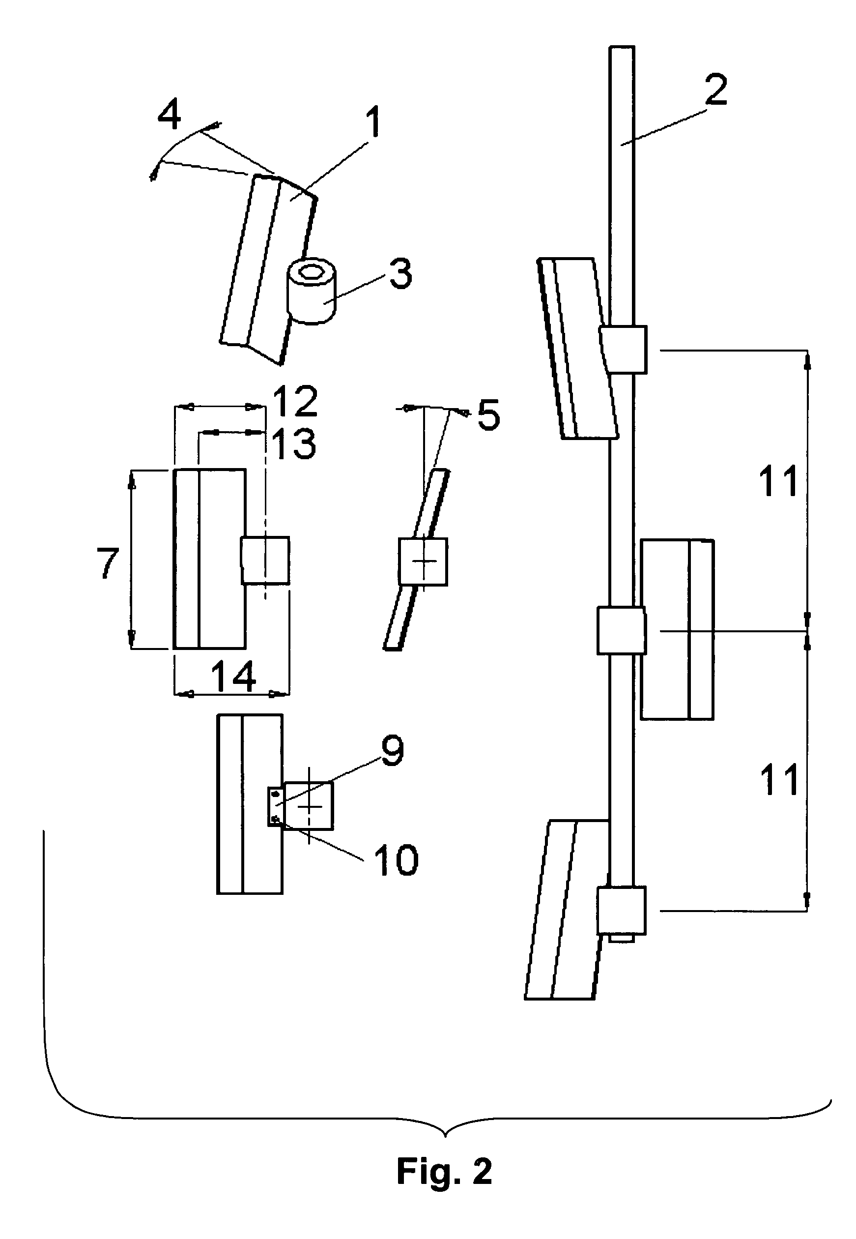
[0030] Referring FIG. 1., an advantageous configuration of an impeller comprises two symmetrical blades 1 arranged diametrically opposite one another (offset by 180°) and attached to a rotatable driving shaft 2 by a hub 3. Each blade 1 is bent along a line at the radially outer edge of the blade 1 by an angle 4. This bend at angle 4 ...


PUM

PropertyMeasurementUnit
diameteraaaaaaaaaa
degree of mixingaaaaaaaaaa
energyaaaaaaaaaa

Abstract

One or more mixing impellers is carried on a driving shaft received in a mixing vessel. Impeller blades are angularly and/or axially distributed on the shaft and can be single staggered axially-spaced blades or groups of two or more placed angularly around the shaft, e.g., diametrically opposite. Each blade has a radially inner flat plate sloped to produce axial flow, preferably at about 15° from parallel to the rotation axis. An outer plate is joined to the inner plate at a bend line with an angle of about 20° located at about 70% of the outside diameter of the impeller path.

Description

CROSS REFERENCE TO RELATED APPLICATION [0001] This application claims the priority of U.S. Provisional Application Ser. No. 60 / 485,585, filed Jul. 8, 2003.BACKGROUND OF THE INVENTION [0002] 1. Field of the Invention [0003] The invention relates to mixing apparatus for producing blends of liquids, solids suspensions, and gas dispersions, at low and controllable shear. [0004] 2. Prior Art [0005] Various different types of impellers are used for different mixing applications. Among other purposes, mixing may involve any of various procedures in which agitation, flow or other movement is produced in a material, and an impeller affects the movement. Typically the impeller is moved relative to a vessel containing the liquids or solids to be mixed, but that is just one possible configuration. [0006] Mixing often is used in an effort to achieve uniformity of blend or solids suspension, crystallization and dispersion of immiscible fluids or gases, etc., and this disclosure, without limitatio...

Claims


Application Information

Patent Timeline
Patent Type & Authority Applications(United States)
IPC IPC(8): B01F27/906
CPCB01F3/04248B01F3/04531B01F7/00133B01F2003/04673B01F7/18B01F15/00883B01F7/00141B01F23/23121B01F23/233B01F23/23362B01F27/0723B01F27/0724B01F27/90B01F35/531
Inventor ROSZCZENKO, JANUSZWYCZALKOWSKI, WOJCIECH
Owner PHILADELPHIA GEAR
Why Eureka
Try Eureka