

Traffic distribution control apparatus and method
a traffic distribution and control apparatus technology, applied in the field of traffic distribution control apparatus and traffic distribution control method, can solve the problems of insufficient current path, no optimal feasible vector, and insufficient current path, and achieve the effect of reducing the amount of calculations, avoiding the effect of redundant calculation
- Summary
- Abstract
- Description
- Claims
- Application Information
AI Technical Summary
Benefits of technology
Problems solved by technology
Method used
Image

Examples
embodiments
The first to third embodiments of the present invention are described below by referring to FIGS. 9A to 9G, 10A to 10G, 11A to 11G, and 12A to 12C.
first embodiment
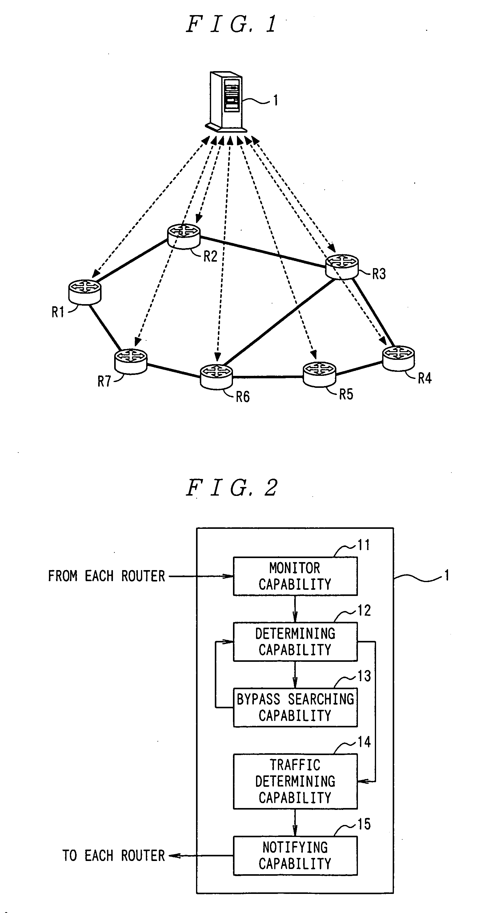
The topology of the network according to the present embodiment is shown in FIG. 9A. In FIG. 9A, the band of the link is 10 Mbps only between the router R2 and the router R3, and 20 Mbps between other routers. Assume that the network resources consumed by each link for unit traffic is 1.
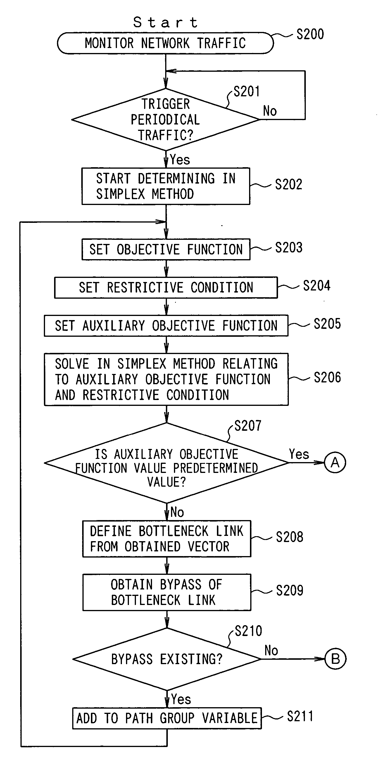
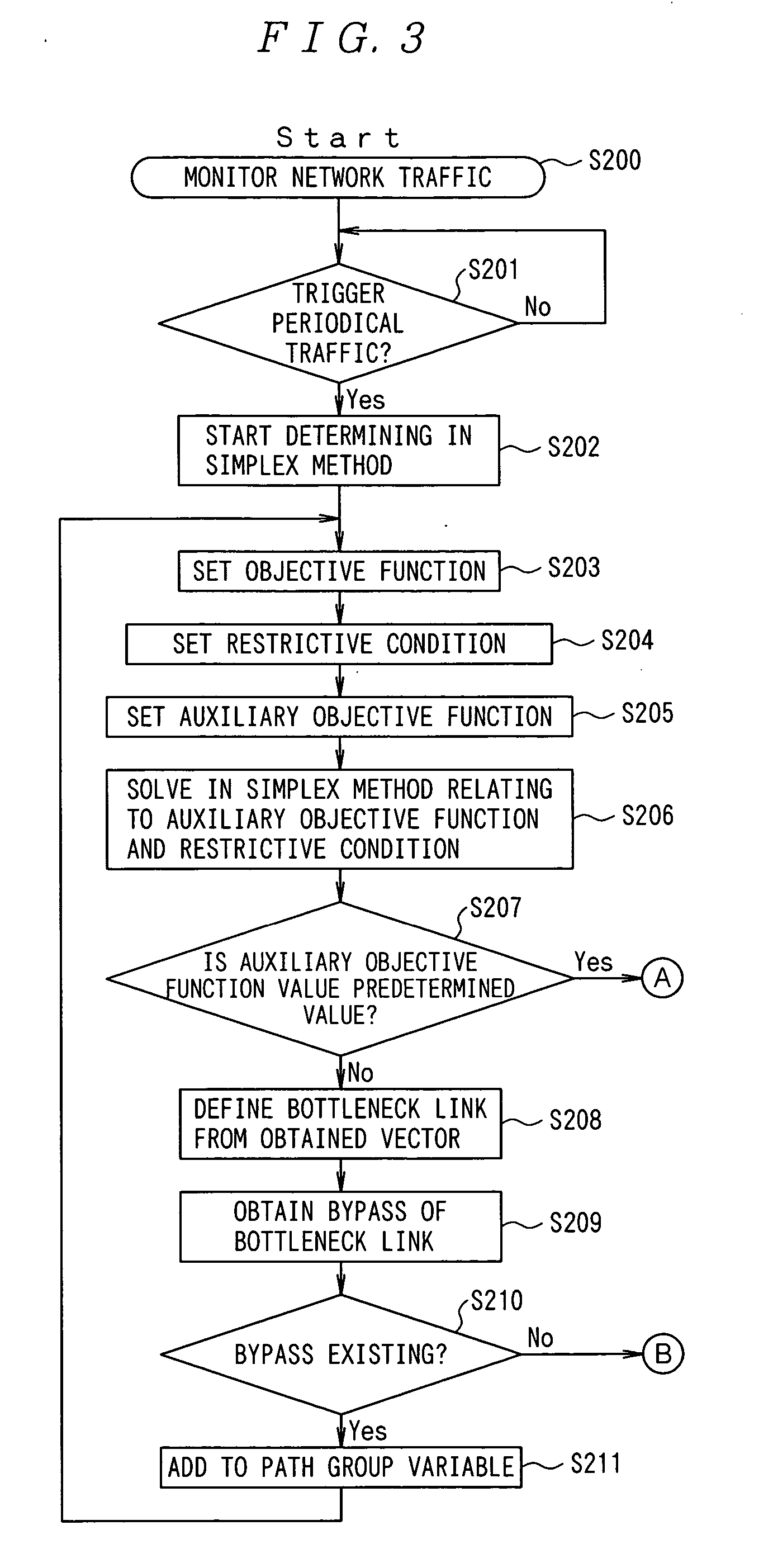
The traffic between the router R1 and the router R4, between the router R2 and the router R4, and between the router R7 and the router R4 is 5 Mbps, respectively. As shown in FIGS. 9B, 9C, and 9D, the currently used paths are a1, b1, and c1. The objective function is set such that the consumption of the network resources can be minimized, and the restrictive condition on the link, the restrictive condition on the traffic amount, and the auxiliary objective function are set, and it is determined whether or not the current link can support the traffic.
As shown in FIGS. 9B, 9C, and 9D, when the problem is solved by the simplex method relating to the objective function f=3a1+2b1+3c1, the feasible ve...
second embodiment
The topology of the network according to the present embodiment is shown in FIG. 10A. In FIG. 10A, the band of the link is 10 Mbps only between the router R2 and the router R3, and 20 Mbps between other routers. Assume that the network resources consumed by each link for unit traffic is 1.
In the present embodiment, there are two classes indicating the priorities. That is, there are classes A and B. The priorities of the classes are class A >class B.
The traffic between the router R1 and the router R4, between the router R2 and the router R4, and between the router R7 and the router R4 is 5 Mbps for the classes A and B respectively. As shown in FIGS. 10B, 10C, and 10D, the currently used paths are a1, b1, and c1. The objective function is set such that the consumption of the network resources can be minimized, and the restrictive condition on the link, and the restrictive condition on the traffic amount are set.
If there is a quality request to transmit the traffic of class A th...
PUM
 Abstract
Description
Claims
Application Information