One natural consequence was that compatibility problems and standards-compliance problems occurred relatively rarely, and another was that barriers to entry often reduced or eliminated competition in particular markets.
If an IP packet is lost, nothing about the IP standard will detect the loss.
Some media have complex access mechanisms.
For example, CSMA controlled media, such as Ethernets, have fairly intricate access procedures that cause delays often larger than the raw
propagation time.
Some packets may experience an unimpeded ride through the net while others may encounter various delays.
With the above-mentioned trends come potential problems.
With the growth of
the Internet, it became impossible to carry out an “N-squared” demonstration in which each of N devices could be tested for
interoperability with the other N−1 devices (and indeed with a device of its own kind), due, among other things, to N becoming very large.
In the particular case of TCP
connectivity, it became clear that while most TCP stacks performed their desired functions fairly reliably when presented with a connection made up of “ordinary” data, some of them did not perform well in the event of connections made up of inputs that, while standards-compliant, were somewhat out of the ordinary.
None of these approaches suffices by itself to test fully the standards compliance of a node, and even these approaches taken together do not lead to complete confidence as to standards compliance.
If a design or body of code is simply lacking a way to test for a boundary condition, for example, this is easy to miss.
But the fraction of this
universe composed of persons who are very good at reviewing the latter types of systems (systems with timing issues, race conditions, asynchronous inputs) turns out to be extremely small.
There are not enough of them, for example, to do even a small proportion of the design reviews and code reviews that would be needed to for comprehensive standards-compliance reviews of Internet-related products.
While protocol test suites are an important part of testing nodes, they cannot test all or even most of the ways in which a node may be improperly designed.
Traffic generators can also be important but again are unlikely to detect subtle design errors.
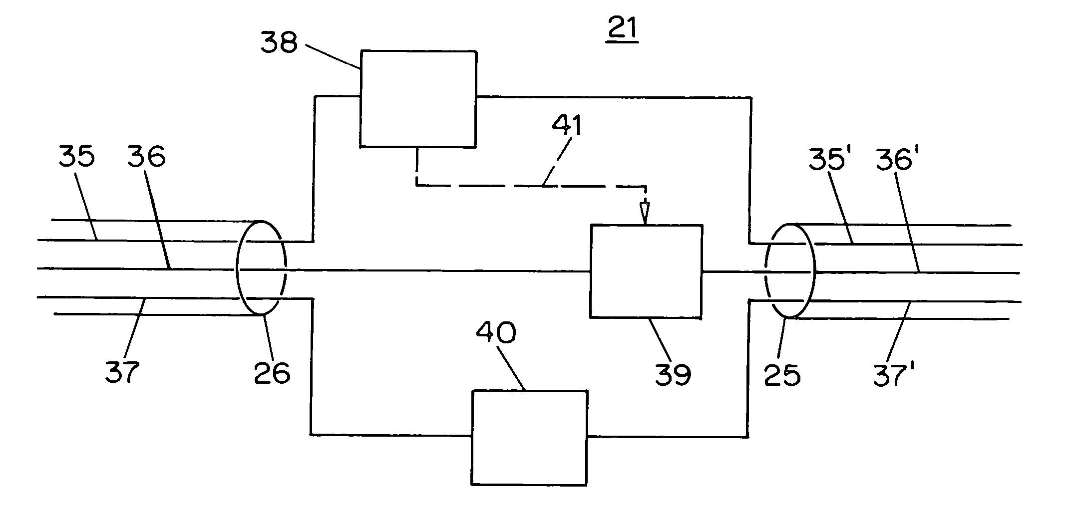
Such traffic generators are not designed to act as an intermediary between two nodes, are not designed to receive packets from multiple sources, do not modify packets based on predetermined or user-controlled criteria, or resend packets which have been intercepted and then modified.
Further, as their function has been limited to simple manipulations only within a single protocol, they do not fully test all of the ways in which a node may fail to
handle standards-compliant but infrequent events.
This gives rise to a concern that a node from among the first wave may function as expected at first, but may fail to function properly as later-designed nodes commence being put into service.
For example, dynamic routing protocols such as BGP can lead to abrupt changes in the routing of packets during a particular voice conversation, raising the question of how the
terminal equipment will
handle such changes.
Prior-art test devices do not provide full answers to these questions.
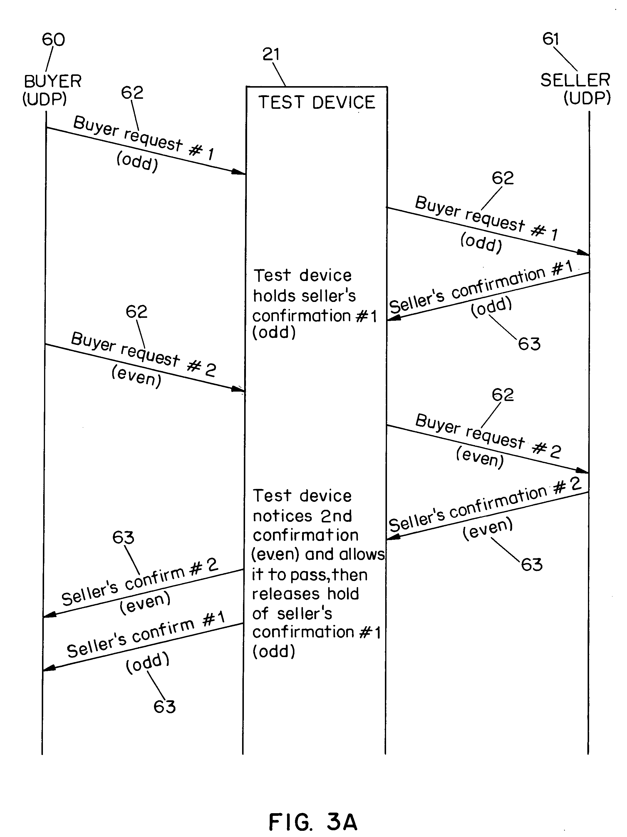
Yet another problem of long-standing duration arises from the development of standards which define more than one connection running in parallel (simultaneously).
But it is not enough for each connection, taken by itself, to deal with dropped or delayed or out-of-order packets.
Yet another problem of long standing arises from the fact that there are whole categories of design mistakes that are simply not detected if the suite of tests is limited to dropped, delayed, corrupted, duplicated or reordered packets.

