
System and method for fabricating bragg gratings

Inactive Publication Date: 2005-01-13
PROXIMON FIBER SYST
View PDF10 Cites 3 Cited by
  • Summary
  • Abstract
  • Description
  • Claims
  • Application Information

AI Technical Summary

Benefits of technology

[0011] According to the inventive method, a blazing angle could be chosen arbitrarily, without any equipment restrictions. Further, the quality and precision of the photo-induced pattern is improved, since the line focus coincides with the fiber even at large blazing angles. Still further, the control of the fabrication process becomes simplified, rendering the fabrication more efficient and less costly, and with a shortening of fabrication times for complex gratings.
[0015] According to one embodiment of the invention, the beams are focused on the fiber by means of at least one lens and the rotation of the beam plane is achieved by displacement of at least one of the beam incidence positions on said lens. The beam incidence position could preferably be displaced in a direction essentially perpendicular to the fiber direction. Hereby, the beams could be displaced on the lens, and still be focused on the fiber. Hence, the angle of incidence relative to the fiber could be varied without affecting the focus.
[0020] According to the invention, a blazing angle could be chosen arbitrarily, without any equipment restrictions. Further, the quality and precision of the photo-induced pattern is improved, since the line focus coincides with the fiber even at large blazing angles. Still further, the control of the fabrication process becomes simplified, rendering the fabrication more efficient and less costly, and with a shortening of fabrication times for complex gratings.

Problems solved by technology

Such blazed Bragg gratings are difficult to fabricate efficiently and with appropriate precision with previously know methods and apparatuses.
However, there are several problems with these known methods.
To be able to tilt the projection system relative to the fiber the equipment becomes complex and costly.
Further, it is difficult to achieve an adequate focus on the fiber in the whole exposure area.
Hereby, the known methods becomes slow and inefficient, with a low through-put.
Still further, with the known methods it is only possible to produce blazed gratings with a limited blazing angle, whereas blazed gratings with larger angles of inclination is very complicated to produce, or even not possible to produce at all.

Method used


Image

  • System and method for fabricating bragg gratings
  • System and method for fabricating bragg gratings
  • System and method for fabricating bragg gratings

Examples


Embodiment Construction

[0029] Further scope of the applicability of the present invention will become apparent from the detailed description given hereinafter. However, it should be understood that the detailed description and specific examples, while indicating preferred embodiments of the invention, are given by way of illustration only, since various changes and modifications within the spirit and scope of the invention will become apparent to those skilled in the art from this detailed description.

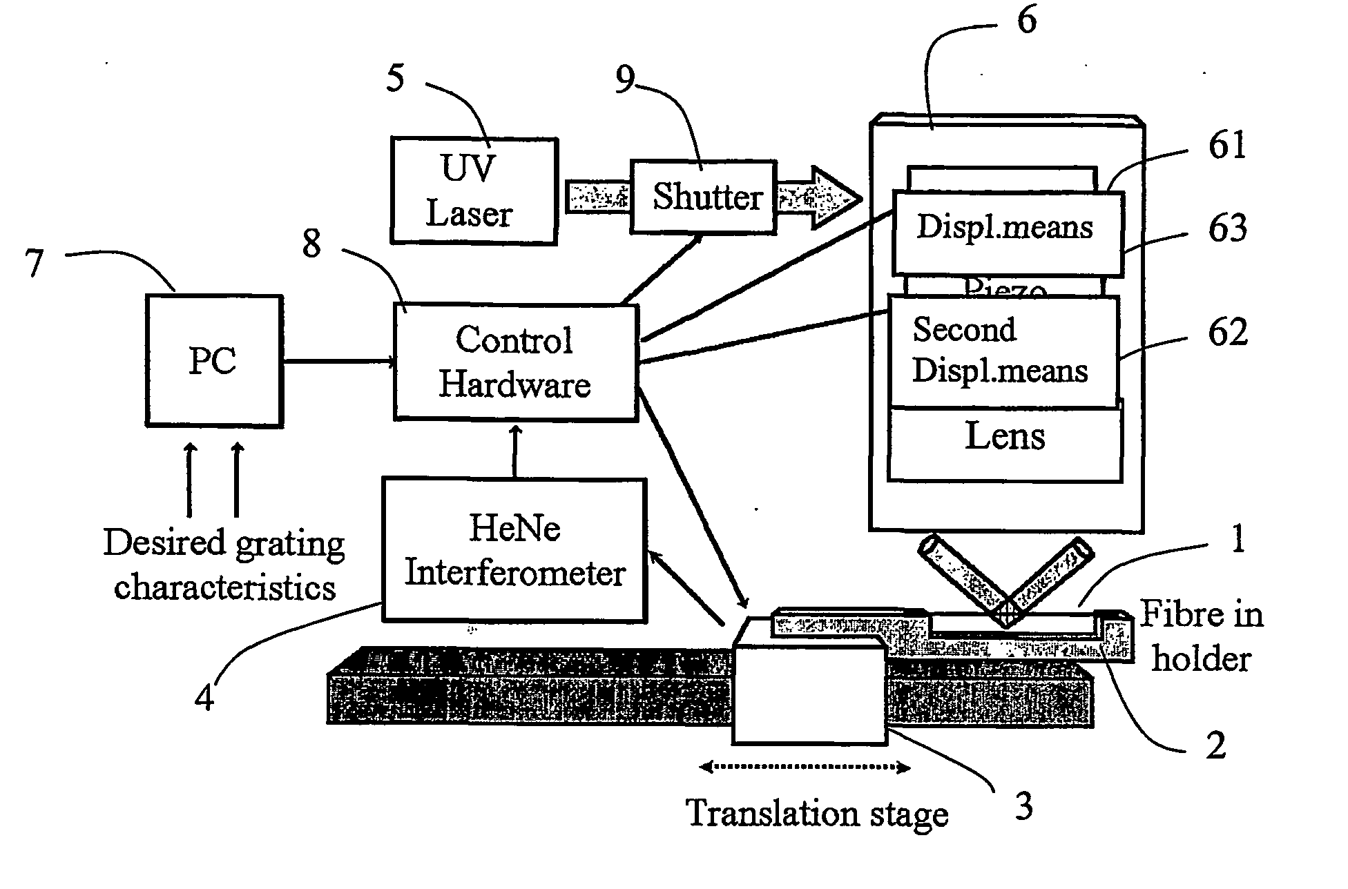
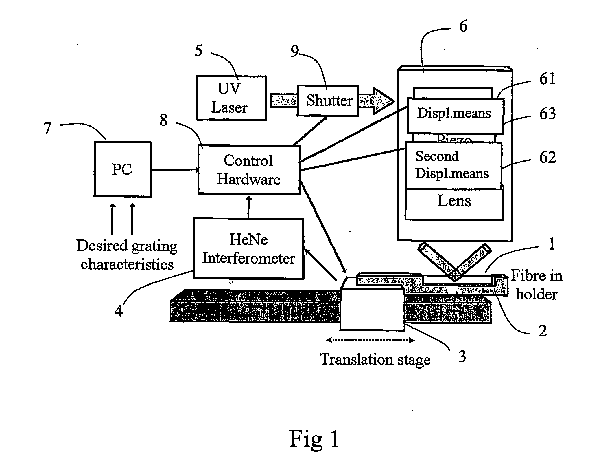
[0030] The setup according to an embodiment of the invention is illustrated in FIG. 1. The base for the system according to the invention could e.g. be a system as described in “Fiber Bragg Gratings” by Raman Kashyap, p. 55-101. Especially the system described with reference to FIG. 3.21 serves as a good base. This description is hereby incorporated by reference.

[0031] However, other types of photo-inducing systems are conceivable for the invention. A system according to the invention comprises in general ...


PUM


Abstract

A novel method and apparatus for fabrication of blazed and slanted fiber Bragg gratings is disclosed. The method comprises the step of simultaneously exposing the fiber with two mutually coherent light beams so as to create an interference pattern along a longitudinal axis of the fiber, wherein each one of said beams is brought into a line focus, which coincides with the core of the fiber. Further, the plane comprising the beams is rotated to provide a second angle relative to the fiber direction, said rotation giving rise to a blazing angle of the photo-induced grating elements.

Description

FIELD OF THE INVENTION [0001] The present invention relates to a method for photo-inducing a blazed grating in an optical fiber comprising the step of simultaneously exposing the fiber with two mutually coherent light beams, which intersects with an first angle in a plane comprising the beams and interfere in a predetermined region of the fiber so as to create an interference pattern along a longitudinal axis of the fiber. The invention further relates to an apparatus for performing the method. BACKGROUND OF THE INVENTION [0002] There is a rapidly growing demand for high-quality optical Bragg gratings with arbitrary phase and index profiles, as these gratings are key elements in many components that are used in WDM networks. Over the past few years, several methods that improve the quality and the flexibility in the grating fabrication process have been developed. A straightforward approach is to scan a UV beam over a long phase mask in a fixed relative position to the fiber. Non-un...

Claims


Application Information

Patent Timeline
IPC IPC(8): G02BG02B6/34
CPCG02B6/02152G02B6/02133
Inventor SAHLGREN, BENGT
Owner PROXIMON FIBER SYST
Features
  • Generate Ideas
  • Intellectual Property
  • Life Sciences
  • Materials
  • Tech Scout
  • Unparalleled Data Quality
  • Higher Quality Content
  • 60% Fewer Hallucinations
Learn More