Developer supply container

a technology for developing and supplying containers, applied in the direction of instruments, electrographic process equipment, optics, etc., can solve the problems of reducing the conveying performance reducing the efficiency of the stirring member, and reducing the frictional turn of the developer into coarse developer, so as to reduce the damage to the developer, the effect of efficient stirring and conveying

Inactive Publication Date: 2005-01-13
CANON KK
View PDF8 Cites 87 Cited by
  • Summary
  • Abstract
  • Description
  • Claims
  • Application Information

AI Technical Summary

Benefits of technology

[0033] The primary object of the present invention is to provide a developer supply container, which is not cylindrical, simple

Problems solved by technology

However, it is extremely difficult to design a stirring member which satisfies all of the above requirements.
However, increasing the pressure a stirring member applied to developer increases the friction between the stirring member and developer, raising therefore the possibility that developer is frictionally turned into coarse developer.
However, decreasing the pressure a stirring member applies to developer results in the decrease in the developer conveying performance of the stirring member, which in turn increases the amount of the developer which cannot be extracted therefrom.
In the case of the abovementioned developer supply container, there is the possibility that a certain amount of developer becomes stuck in the dead spaces, that is, the spaces which the stirring wings (flanges) of the stirring member do not reach, and/or remains adhered to the internal wall of the container proper, failing thereby to be stirred or conveyed; in other words, there is the possibility that a certain amount of developer permanently remains in the developer supply container.
However, each of the stirring member structures disclosed in these patent documents also had its own problems.
However, making such a modification to the stirring member makes the contact pressure (scraping pressure) between the stirring member and the internal surface of the developer supply container even higher in the aforementioned range b, raising the risk of producing coarse developer.
Thus, these countermeasures are not desirable.
In addition, the dimension of the stirring wing in terms of its rotational radius direction becomes too large relative to the dimension optimal for developer conveyance.
In other words, the theoretical entry of the stirring wing into the internal wall of the container proper becomes too large, reducing thereby the stirring member in terms of the e

Method used


Image

  • Developer supply container
  • Developer supply container
  • Developer supply container

Examples


first embodiment

[0046] Next, the developer supply container in the present invention will be described, along with the electrophotographic image forming apparatus in which the developer supply container is mountable.

embodiment 1

[0047] Embodiment 1

[0048] {General Structure of Image Forming Apparatus}

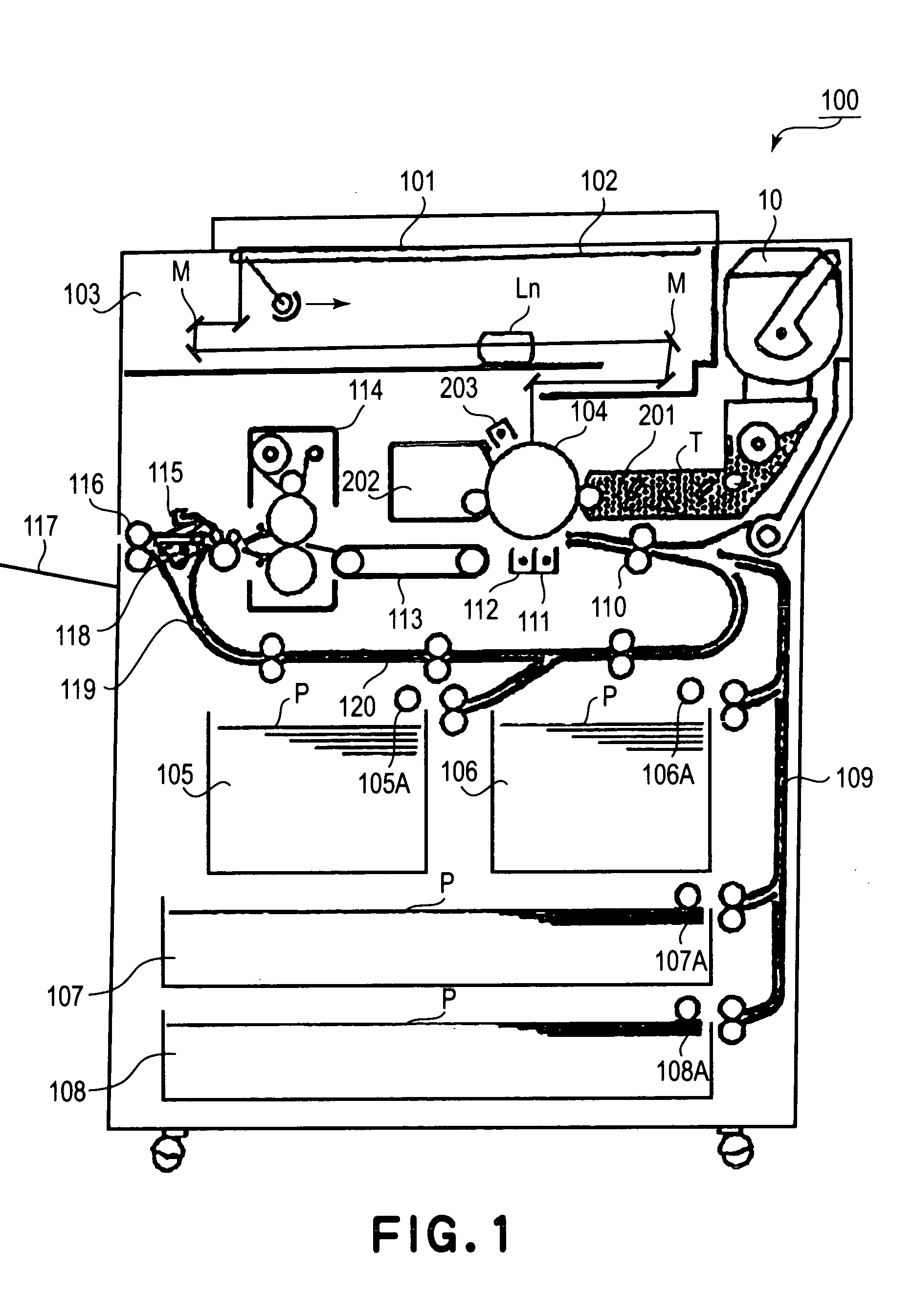
[0049] First, referring to FIG. 1, the structure of a typical electrophotographic copying apparatus in which the developer supply container in the first embodiment of the present invention is mountable will be described.

[0050] In FIG. 1, designated by a referential number 100 is the main assembly of an electrophotographic copying machine (which hereinafter may be referred to simply as “apparatus main assembly”). Designated by a referential number 101 is an original placed on an original placement platen 102 so that the optical image of the original 101, which carries the data necessary for forming an image of the original 101, is formed on the peripheral surface of the photosensitive drum 104 by the multiple mirrors M and lens Ln of the optical portion 103. Designated by referential numbers 105-108 are cassettes for sheets P of recording medium. Among these cassettes 105-108, the cassette which contains the she...

embodiment 2

[0153] Embodiment 2

[0154] Next, referring to FIG. 9, the second embodiment of the present invention will be described.

[0155]FIG. 9 is a sectional view of the developer supply container 10 in the second embodiment of the present invention, at a plane perpendicular to the stirring wing support shaft 17.

[0156] The developer supply container 10 in this embodiment is an example of a developer supply container in accordance with the present invention, characterized in that due to the restrictions resulting from the design of the main assembly 100 of the image forming apparatus, the opposing two lateral walls of the container proper 11 are angled relative to the top wall of the container proper 11, as shown in FIG. 9, and also, that the container proper 11 is not cylindrical.

[0157] This developer supply container 10 was subjected to the experiments similar (except for the amount (roughly 200 g) of developer T with which developer supply container was filled) to those to which the develo...


PUM


Abstract

A developer supply container detachably mountable to an image forming apparatus, includes a container body, having a non-circular cross-section, for containing a developer, the container body having an arcuate portion and an extension upwardly extending from the arcuate portion; a discharge opening, formed in the arcuate portion for discharging the developer from the container body; a stirring member for in stirring the developer in the container body, the stirring member having a rotation shaft provided in the arcuate portion and a flexible resin material sheet mounted on the rotation shaft; wherein the flexible resin material sheet includes a feeding blade for feeding the developer toward the discharge opening, the feeding blade being slidable relative to an inner surface of the arcuate portion and being non-slidable relative to a ceiling portion of an inner surface of the extension, and includes a stirring blade for stirring the developer, the stirring being slidable relative to a ceiling portion of the inner surface of the extension.

Description

FIELD OF THE INVENTION AND RELATED ART [0001] The present invention relates to a developer supply container employed by an electrophotographic or electrostatic image forming apparatus, for example, a copying machine, a printer, facsimileing machine, etc. [0002] Generally, an image forming apparatus such as an electrophotographic copying machine or a laser beam printer records an image through the following processes: a process in which a latent image is formed on the uniformly charge peripheral surface of the photosensitive drum by selectively exposing a numerous number of points of the uniformly charge area of the photosensitive drum; a process in which the latent image is developed by developer into an image formed of the developer (toner); and a process in which the developer (toner) image is transferred onto recording medium. [0003] Thus, each time an image forming apparatus such as the one descried above runs out of developer, it must be supplied with developer. In order to sup...

Claims


Application Information

Patent Timeline
IPC IPC(8): B65D83/06G03G15/08
CPCG03G2215/068G03G2215/085G03G15/0855G03G15/0865G03G15/0875
Inventor TAZAWA, FUMIONAGASHIMA, TOSHIAKINAKAJIMA, NOBUO
Owner CANON KK
Why Eureka
Try Eureka