
Roadway projecting marker

a technology of road projecting markers and speed bumps, which is applied in the direction of roads, signalling systems, constructions, etc., can solve the problems of concrete speed bump devices breaking, affecting the safety of drivers or pedestrians, and causing the driver's family to be ups

Inactive Publication Date: 2005-01-13
CHEN SHIN MIN
View PDF6 Cites 10 Cited by
  • Summary
  • Abstract
  • Description
  • Claims
  • Application Information

AI Technical Summary

Benefits of technology

[0013] The main objective of the invention is to provide a speed bump assembly to increase drivers' alertness and to draw the drivers' attention to the condition of the road by means of the protruding speed bump assembly.
[0014] A further objective of the invention is to provide a speed bump assembly to make the driver quickly aware of the condition of the road by means of reflected light.
[0015] Another objective of the invention is to provide a speed bump assembly that is useful and will not cause toxic material to damage the environment and people's health over long term use.

Problems solved by technology

Traffic accidents are an economic loss to society and will cause sorrow for the driver's family.
However, each aforementioned conventional technique has a specific disadvantage that causes danger to a driver or a pedestrian.
For example, the concrete speed bump device will break up after long-term use or being run over by vehicles.
This will shock the driver in the car struck and cause an accident.
The asphalt and painted speed bumps are easily softened high ambient temperature, and the warning effect of the speed bump device will be lost.
In addition, the paint will give off volatile toxic gas due to high ambient temperature and seriously influence the environment and people's health.
The conventional plastic speed bump easily deforms, deteriorates or breaks into pieces due to the high ambient temperature, and the plastic reflection tab will detach from the speed bump and be another hazard to the driver.
The conventional plastic speed bump has a smooth surface and does not provide good friction, so the vehicle easily slips when the driver changes lanes.
In addition, huge vibrations and loud noise will occur when the wheels of vehicles strike the aluminum reflection tab, which will damage wheels and cause accidents.
Furthermore, to repair the damaged conventional speed bumps is labor intensive.
The material used to repair the damaged speed bump device will not match the deteriorated material of the damaged speed bump and easily detaches from the deteriorated material.
In addition, the conventional speed bump does not provide an excellent noise-absorbing effect, such that loud noise will occur when vehicles passes through the speed bump.

Method used


Image

  • Roadway projecting marker
  • Roadway projecting marker
  • Roadway projecting marker

Examples


Embodiment Construction

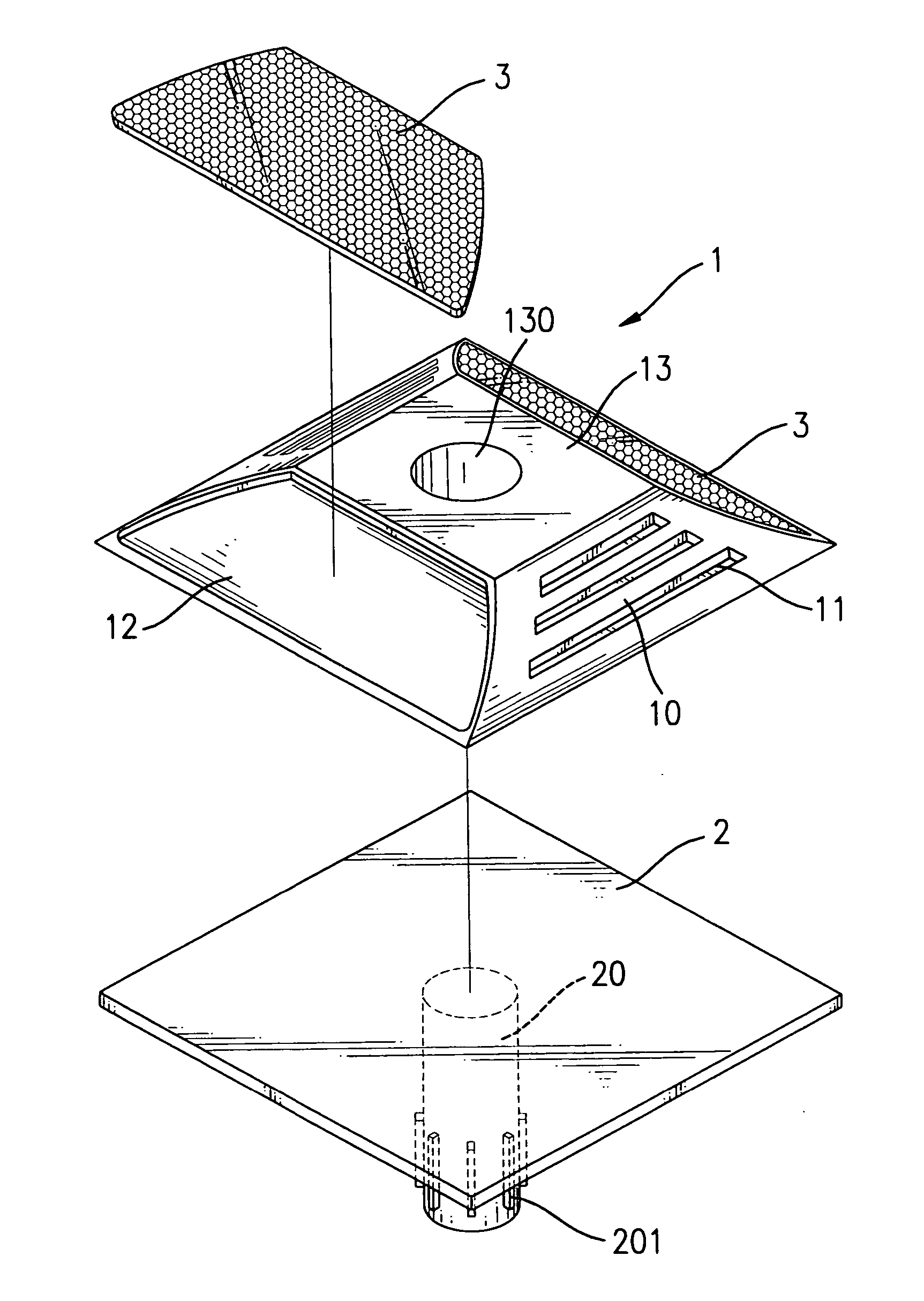
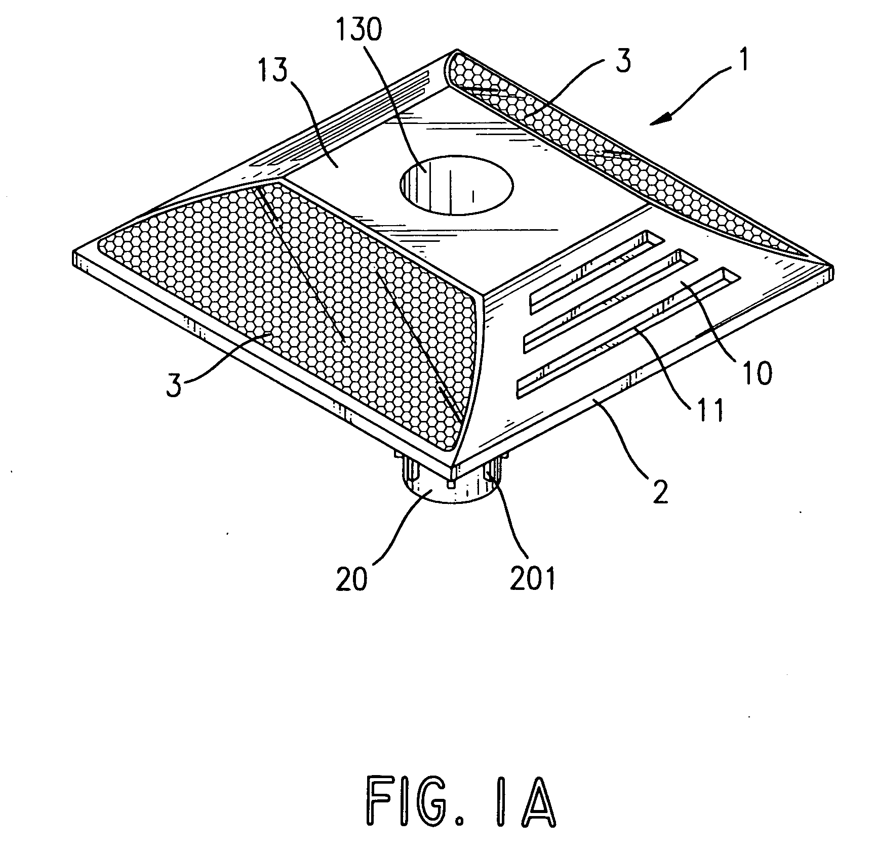
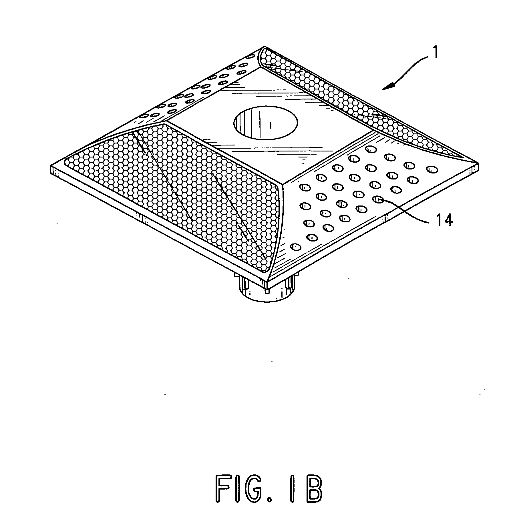
[0036] With reference to FIGS. 1A and 1B, a speed bump assembly on a road surface in accordance with the present invention comprises a speed bump (1). The speed bump (1) has a bottom attached to a metal base (2) to make the bottom of the speed bump (1) flush with the road surface to achieve a stable effect. The speed bump (1) has a tapered structure and has recesses (10) and grooves (11) defined in sides thereof, as shown in FIG. 1 or holes (14) defined in sides thereof, as shown in FIG. 1B.

[0037] The recesses (10), grooves (11) and holes (14) increase the shock and noise absorbing effect and save material during manufacturing. In addition, two engaging recesses (12) are defined respectively in opposite sides to receive reflection tabs (3) to provide a reflecting warn effect. The speed bump (1) has a flat top surface (13) with a driving hole (130) for a special design of the road surface. A cone-shaped object is inserted into the driving hole (130) to drive a metal stub (20) on the...


PUM


Abstract

A speed bump assembly on a road surface provides a sign to a driver to slow down a car and a warning effect to the driver. The speed bump has a tapered structure and has recesses, grooves or holes defined in opposite sides to enhance shock-absorbing, noise-absorbing and nonskid. Two reflection tabs are attached respective to the opposite sides of the speed bump to provide a warning and reflective effect to a driver to draw the driver's attention when driving. A metal base is attached to the bottom of the speed bump to keep the plastic speed bump from deforming due to expansion when hot and shrinking when cold and to enhance the strength of combination between the road surface.

Description

[0001] This application is the National Stage of international application No. PCT / CN01 / 01480, filed on Oct. 15, 2001.BACKGROUND OF THE INVENTION [0002] 1. Field of the Invention [0003] The present invention relates to a speed bump assembly, and more particularly to a speed bump assembly mounted on a road surface and on division lines to provide a sign to a driver to slow down a car and to call the driver's attention to safety in driving. [0004] 2. Description of Related Art [0005] Traffic accidents are always one of the top 10 reasons for death in many countries and easily occur when a driver exceeds the speed limit or dozes off. Traffic accidents are an economic loss to society and will cause sorrow for the driver's family. [0006] However, to call driver's attention and improve driving safety, speed bumps are mounted at intersections or merges to superhighways. In addition, protrusions are always mounted on division lines on road surfaces to warn drivers to notice road conditions ...

Claims


Application Information

Patent Timeline
Patent Type & Authority Applications(United States)
IPC IPC(8): E01F9/553
CPCE01F9/06E01F9/553
Inventor CHEN, SHIN-MIN
Owner CHEN SHIN MIN
Learn More