
Multi-functional composite structure and process of its production

a composite structure and multi-functional technology, applied in the field of composite structure, can solve the problems of prior art documents not disclosing the functionalities of interior lining parts, and prior art documents not disclosing the use of translucent layers hiding functional regions

Pending Publication Date: 2021-07-08
TMG - TECIDOS PLASTIFICADOS E OUTROS REVESTIMENTOS PARA A IND AUTOMOVEL
View PDF1 Cites 1 Cited by
  • Summary
  • Abstract
  • Description
  • Claims
  • Application Information

AI Technical Summary

Benefits of technology

The present invention relates to a composite structure that uses touch sensors to replace conventional buttons, resulting in a seamless surface. The structure can also include decorative or indicative patterns, which can be colored to improve user orientation or attract user attention. The touch sensors can be hidden-until-lit, making the structure more visually appealing when not in use. These features provide new design options for the composite structure.

Problems solved by technology

These prior art documents do not disclose an interior lining part having functionalities other than lighting.
These prior art documents do not disclose the use of translucent layers hiding the functional regions.

Method used


Image

  • Multi-functional composite structure and process of its production
  • Multi-functional composite structure and process of its production
  • Multi-functional composite structure and process of its production

Examples


example

[0165]The present invention will be illustrated by the following example.

[0166]A two-step process was carried out to produce a composite structure. In a first step, a black opaque mask of a plastisol was screen printed onto a translucent TPU foil placed on a flat bed to obtain a modified TPU foil, as illustrated in FIG. 7. In a second step, touch sensors were screen printed onto the mask on the modified TPU foil. The touch sensors were commercially available membrane touch switches made of silver (DuPont 5025). The curing was carried out for 10 minutes at 100° C. An electrode and a ground connection were mounted to the composite structure.

[0167]The composite structure obtained by this process is illustrated in FIG. 5 showing an exploded view of a composite structure.

[0168]FIGS. 8A and 8B illustrate the advantageous effects of the composite structure, particularly the hidden-until-lit property of the composite structure.

Reference Numerals

[0169](1) translucent layer

[0170](2) opaque la...


PUM

PropertyMeasurementUnit
light transmittanceaaaaaaaaaa
thicknessaaaaaaaaaa
thicknessaaaaaaaaaa

Abstract

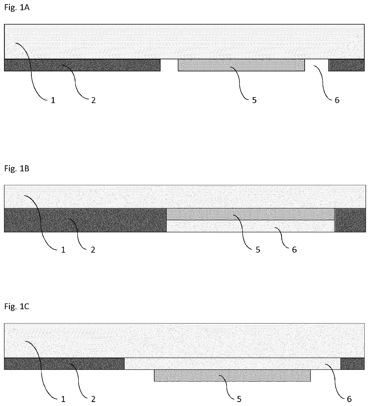
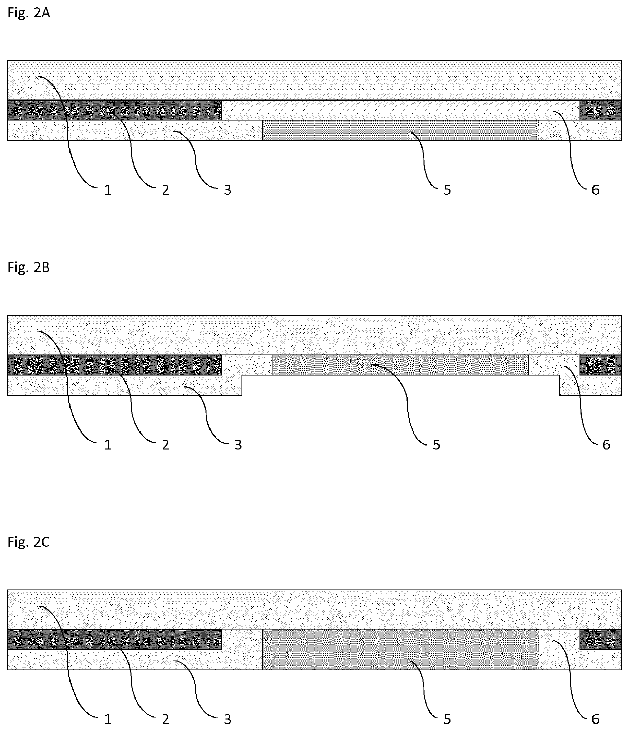
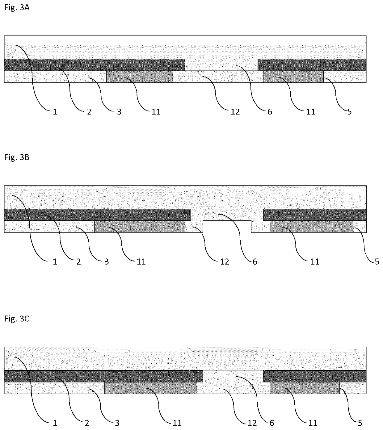
The present invention provides a composite structure comprising a translucent layer (1) having a light transmittance of 1 to 50%, an opaque layer (2) containing a translucent area (6), and a touch sensor area (5) that is at least partly arranged in or above or below the translucent area of layer (2). The present invention also provides a method of producing the composite structure. The composite structure can be used to replace conventional buttons in motor vehicles.

Description

FIELD OF THE INVENTION[0001]The present invention relates to a composite structure comprising a translucent layer (1) having a light transmittance of 1 to 50%, an opaque layer (2) containing a translucent area (6), and a touch sensor area (5) that is at least partly arranged in or above or below the translucent area of layer (2). The present invention also provides a method of producing the composite structure. The composite structure can be used to replace conventional buttons in motor vehicles.BACKGROUND ART[0002]EP 3 088 156 A1 describes a method for producing an illuminable attachment area for a motor vehicle, wherein a light transmitting sheet with a mask layer, opaque except for at least one transmitting area, is coated with such a design that allows light transmitting only in a predetermined proportion of the foil. The advantage of this invention lies in the fact that a foil is provided which is back-moulded in the coated state with a carrier.[0003]EP 3 053 778 A1 describes a...

Claims


Application Information

Patent Timeline
Patent Type & Authority Applications(United States)
IPC IPC(8): B60K35/00B60K37/02B41M1/12B41M5/00
CPCB60K35/00B60K37/02B60K2370/1446B41M5/0047B60K2370/28B41M1/12B29C45/14B60K35/10B60K2360/1446B60K2360/28B60K5/00B60K35/60
Inventor CARVALHO DA SILVA, LUIS FILIPEDA SILVA MAIA, TIAGO FILIPERODRIGUES AGUIA, ANTONIO CESARDE PINHO, ELIZABETE
Owner TMG - TECIDOS PLASTIFICADOS E OUTROS REVESTIMENTOS PARA A IND AUTOMOVEL
Learn More