
Methods of forming a multilayer stack alloy for work function engineering

a technology of work function engineering and multi-layer stack alloy, which is applied in the direction of semiconductor devices, semiconductor/solid-state device details, electrical apparatus, etc., can solve the problems of reducing the strength of the electric field, reducing the performance and reducing the strength of polysilicon gate electrodes

Inactive Publication Date: 2005-01-13
INTEL CORP
View PDF13 Cites 3 Cited by
  • Summary
  • Abstract
  • Description
  • Claims
  • Application Information

AI Technical Summary

Problems solved by technology

However, polysilicon gate electrodes may suffer device performance degradation due to the polysilicon depletion effect, wherein an electric field applied to a polysilicon gate sweeps away carriers (holes in a P-type doped polysilicon, or electrons in an N-type doped polysilicon) so as to create a depletion of carriers in the area of the polysilicon gate near the underlying gate dielectric of the transistor.
This depletion effect results in a reduction in the strength of the electric field at the surface of the microelectronic when a voltage is applied to the polysilicon gate electrode, which can have an adverse affect on the transistor performance.
While replacing traditional polysilicon gate electrodes with metal or metal alloy gate electrodes eliminates the polysilicon depletion effect, there are problems associated with the use of such metal gates.
One problem encountered is that the carriers from the metal gate can diffuse into the underlying gate dielectric material, thus causing shorting of the microelectronic device.
Another problem encountered with the use of metal gates is work function mismatch, wherein the work functions of the metal gate p and n-channel transistors do not match the work functions of the p and n channel transistors of the polysilicon gate.
A drawback to this mid-range work function approach is that this type of metal gate device cannot easily achieve a desirable small threshold voltage, which is the amount of voltage that determines the transistor's on and off states, without causing degradation in device performance.

Method used


Image

  • Methods of forming a multilayer stack alloy for work function engineering
  • Methods of forming a multilayer stack alloy for work function engineering
  • Methods of forming a multilayer stack alloy for work function engineering

Examples


Embodiment Construction

[0010] In the following detailed description, reference is made to the accompanying drawings that show, by way of illustration, specific embodiments in which the invention may be practiced. These embodiments are described in sufficient detail to enable those skilled in the art to practice the invention. It is to be understood that the various embodiments of the invention, although different, are not necessarily mutually exclusive. For example, a particular feature, structure, or characteristic described herein, in connection with one embodiment, may be implemented within other embodiments without departing from the spirit and scope of the invention. In addition, it is to be understood that the location or arrangement of individual elements within each disclosed embodiment may be modified without departing from the spirit and scope of the invention. The following detailed description is, therefore, not to be taken in a limiting sense, and the scope of the present invention is defined...


PUM


Abstract

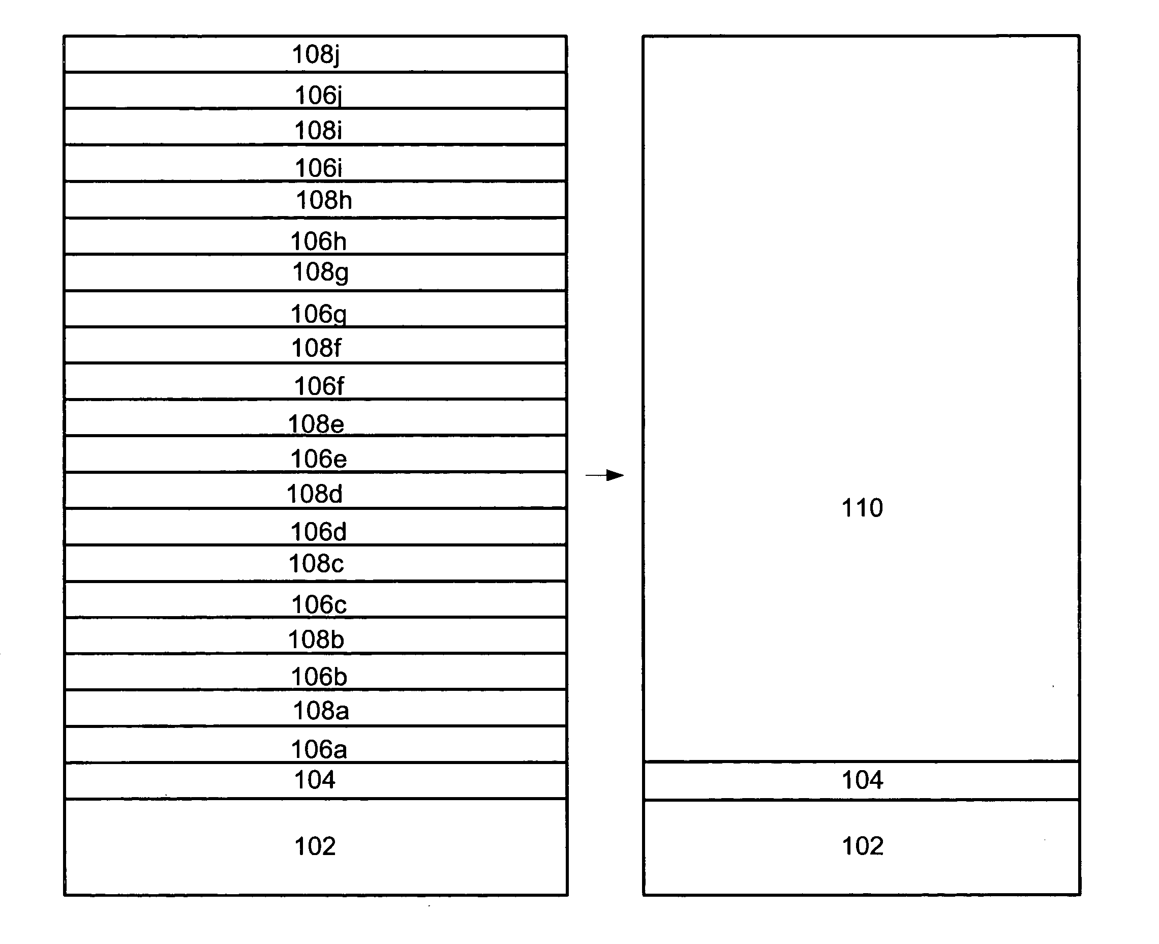
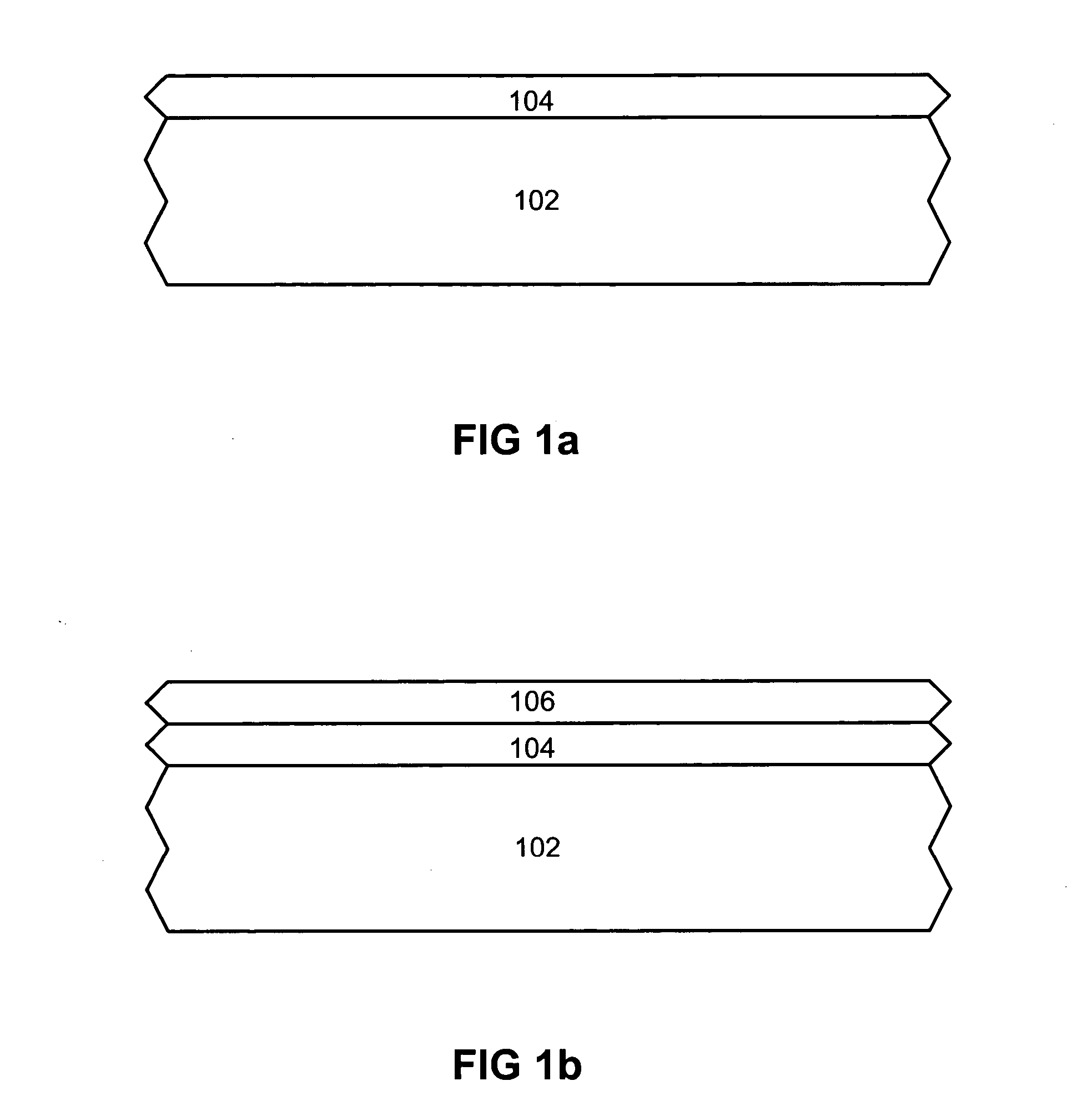
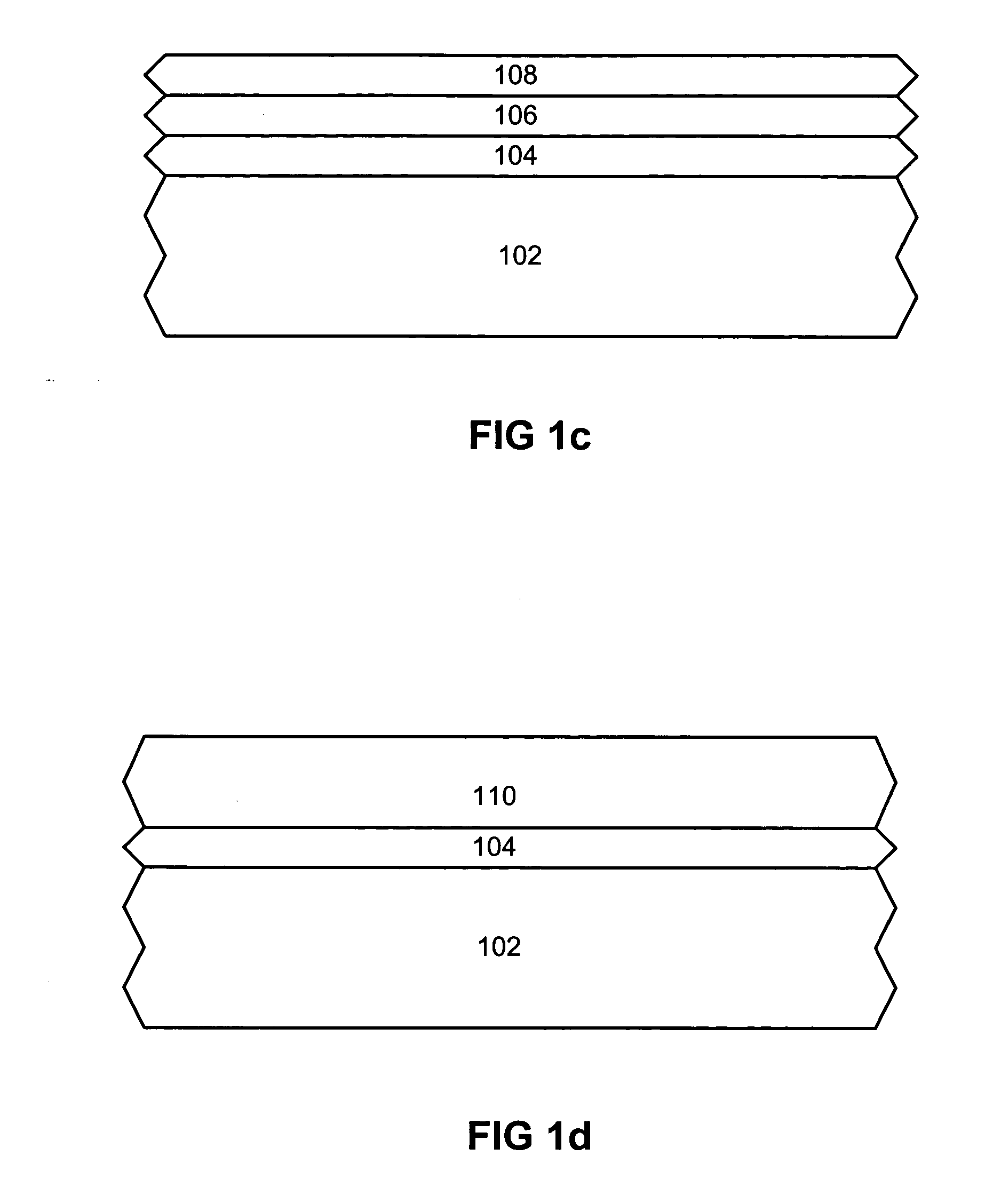
A method of forming a gate electrode is described, comprising forming a dielectric layer on a substrate, forming a first metal layer having a first work function on the dielectric layer, forming a second metal layer having a second work function on the first metal layer, such that a gate electrode is formed on the dielectric layer which has a work function that is determined from the work function of the alloy of the two types of metal. The work function of a microelectronic transistor can be varied or “tuned” depending on the precise definition and control of the metal types, layer sequence, individual layer thickness and total number of layers.

Description

FIELD OF THE INVENTION [0001] The present invention relates to the field of microelectronic processing, and more particularly to a method of work function tuning by forming a gate electrode utilizing a multi-layer single-phase metal alloying technique. BACKGROUND OF THE INVENTION [0002] Transistors, as is well known in the art, are the building blocks of all integrated circuits. Modern integrated circuits interconnect literally millions of densely configured transistors that perform a wide variety of functions. To achieve such a dramatic increase in the density of circuit components has required microelectronic manufacturers to scale down the physical dimensions of the transistor below the sub-micron regime. One common type of transistor used in a sub-micron microelectronic device utilizes a polysilicon gate electrode. However, polysilicon gate electrodes may suffer device performance degradation due to the polysilicon depletion effect, wherein an electric field applied to a polysil...

Claims


Application Information

Patent Timeline
IPC IPC(8): H01L21/28H01L29/49
CPCH01L29/4966H01L21/28088
Inventor BARNAK, JOHNBORLA, COLLINDOCZY, MARKKUHN, MARKUSJENSEN, JACOB M.
Owner INTEL CORP
Learn More