
Apparatus and methods for positioning prostheses for deployment from a catheter

a technology of prosthesis and catheter, which is applied in the field of vascular catheters, can solve the problems of coronary artery reoccurring, early stent technology suffered, and current stent delivery technology suffers from a number of drawbacks

Inactive Publication Date: 2005-01-13
JW MEDICAL SYSTEMS LTD
View PDF69 Cites 157 Cited by
  • Summary
  • Abstract
  • Description
  • Claims
  • Application Information

AI Technical Summary

Benefits of technology

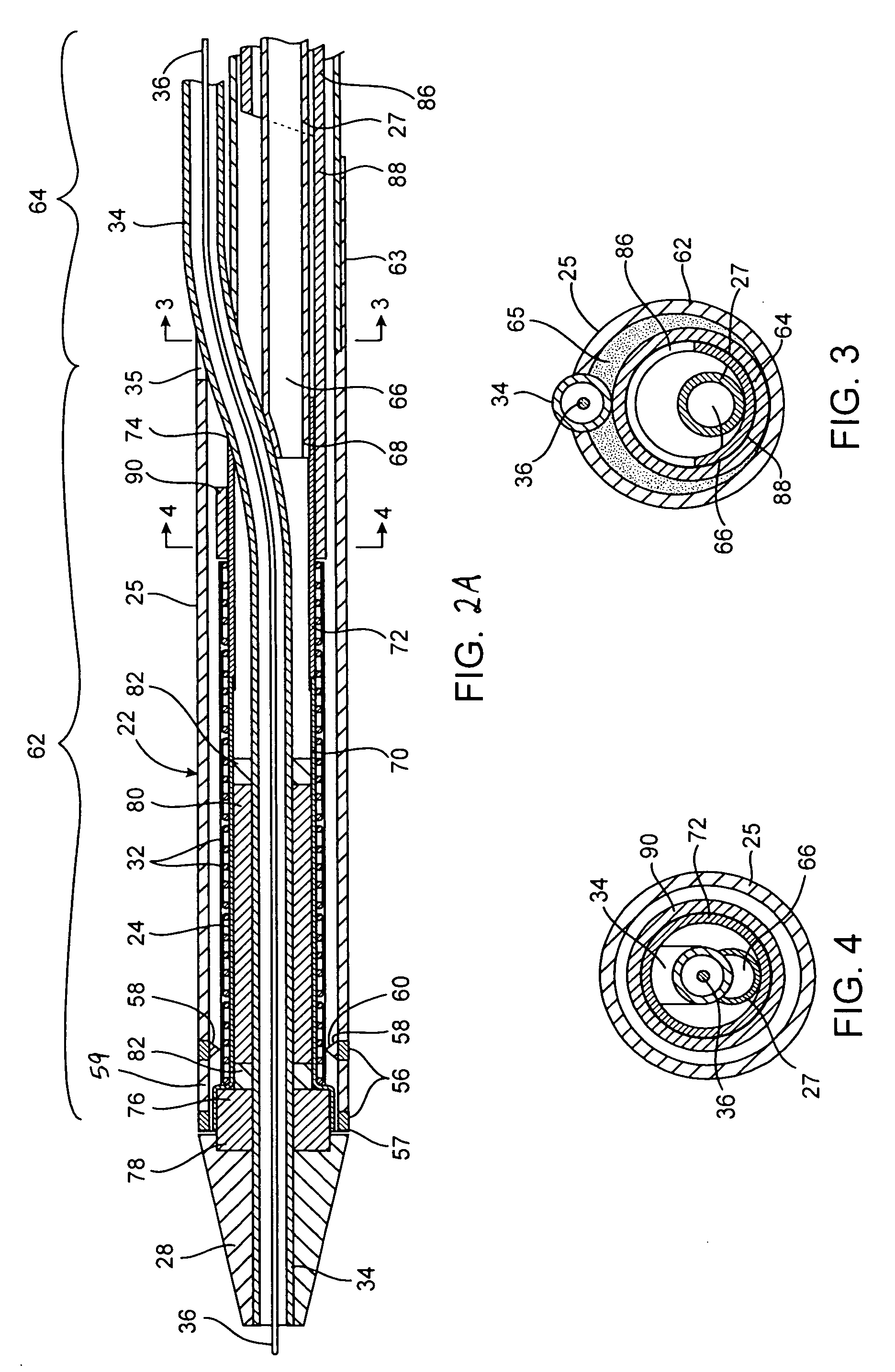
[0017] In yet another embodiment, the stop member comprises a cone shaped member coupled with the catheter shaft inside the expandable member. Alternatively, the stop member may include a movable distal nose cone slidably disposed over the distal end of the catheter shaft from a first position over a distal end of the expandable member to a second position distal to the distal end of the expandable member and an inner shaft slidably coupled to the catheter shaft and attached to the nose cone. In another embodiment, the apparatus further includes a nosecone disposed distally of the expandable member, and the stop member comprises a sleeve extending proximally from the nose cone to cover a distal end of the expandable member. Such a sleeve may optionally be biased, such as with a flexible bend, to dispose a proximal end of the sleeve within a sheath of the apparatus, to thus avoid the proximal end of the sleeve from catching on the distal end of the sheath.
[0018] In alternative embodiments, the at least one stop member comprises one or more surface features on a distal portion of the expandable member. In some embodiments, for example, the surface features may include but are not limited to bumps, ridges, spines, ribs, scales, pleats and wings. In another embodiment, the surface feature comprises a thickened distal portion of the expandable member, the thickened distal portion including a proximal abutment. In other embodiments, the surface features comprise at least one material selected from the group consisting of Dacron, C-flex, high friction materials, gels and adhesives.

Problems solved by technology

Early stent technology suffered from problems with restenosis, the tendency of the coronary artery to become re-occluded following stent placement.
Current stent delivery technology, however, suffers from a number of drawbacks.
For example, current stent delivery catheters are not capable of customizing the length of the stent in situ to match the size of the lesion to be treated.
While lesion size may be measured prior to stenting using angiography or fluoroscopy, such measurements may be inexact.
Moreover, current stent delivery devices cannot treat multiple lesions with a single catheter.
Further, current stent delivery devices are not well-adapted for treating vascular lesions that are very long and / or in curved regions of a vessel.
If current stents were made longer so as to treat longer lesions, they would not conform well to the curvature of vessels or to the movement of vessels on the surface of the beating heart.
On the other hand, any attempt to place multiple stents end-to-end in longer lesions is hampered by the inability to maintain appropriate inter-stent spacing and to prevent overlap of adjacent stents.
Additionally, some stent delivery catheters and angioplasty balloon catheters, particularly those having movable external sheaths to enclose the stent or balloon, suffer from poor tracking and cumbersome interaction with guidewires.
Some such catheters utilize an “over-the-wire” design in which the guidewire extends through an inner lumen of the catheter from its proximal end to its distal end, a design that makes catheter exchanges cumbersome and time-consuming.
However, in these designs the guidewire inhibits smooth retraction of the sheath and, if the sheath is retracted a substantial distance, the port can become so displaced from the distal end of the catheter that the guidewire does not slide smoothly as the catheter is moved.
Currently available catheters, however, do not typically provide for positioning stents on a balloon in situ.
If a stent is advanced over a balloon on a catheter positioned in a vessel, it is often difficult or impossible to determine how far the stent should be advanced relative to the balloon.
A stent may be advanced too far, pushing it off the distal end of the balloon, so that all or a portion of the stent does not expand properly with balloon expansion.
At other times, a stent may not be advanced far enough along the balloon, in which case the balloon portion not covered by stent material (known as “balloon overhang”) may dilate the vessel when expanded, potentially causing trauma to the vessel.
Finally, many stent delivery catheters suffer from inflexibility and high cross-sectional profile, which hamper endovascular positioning.

Method used


Image

  • Apparatus and methods for positioning prostheses for deployment from a catheter
  • Apparatus and methods for positioning prostheses for deployment from a catheter
  • Apparatus and methods for positioning prostheses for deployment from a catheter

Examples


first embodiment

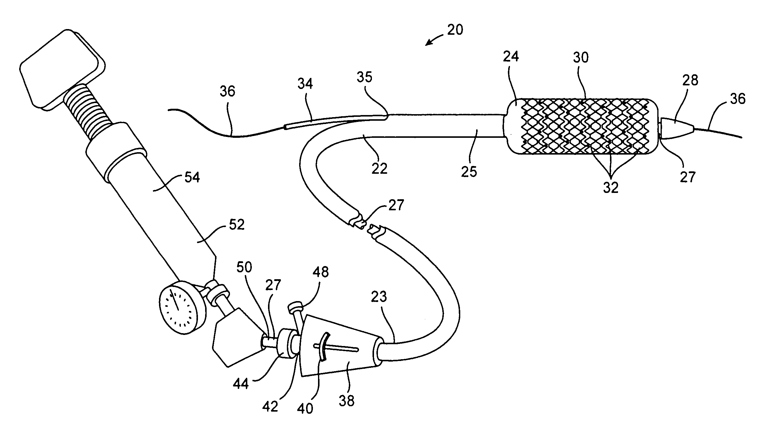
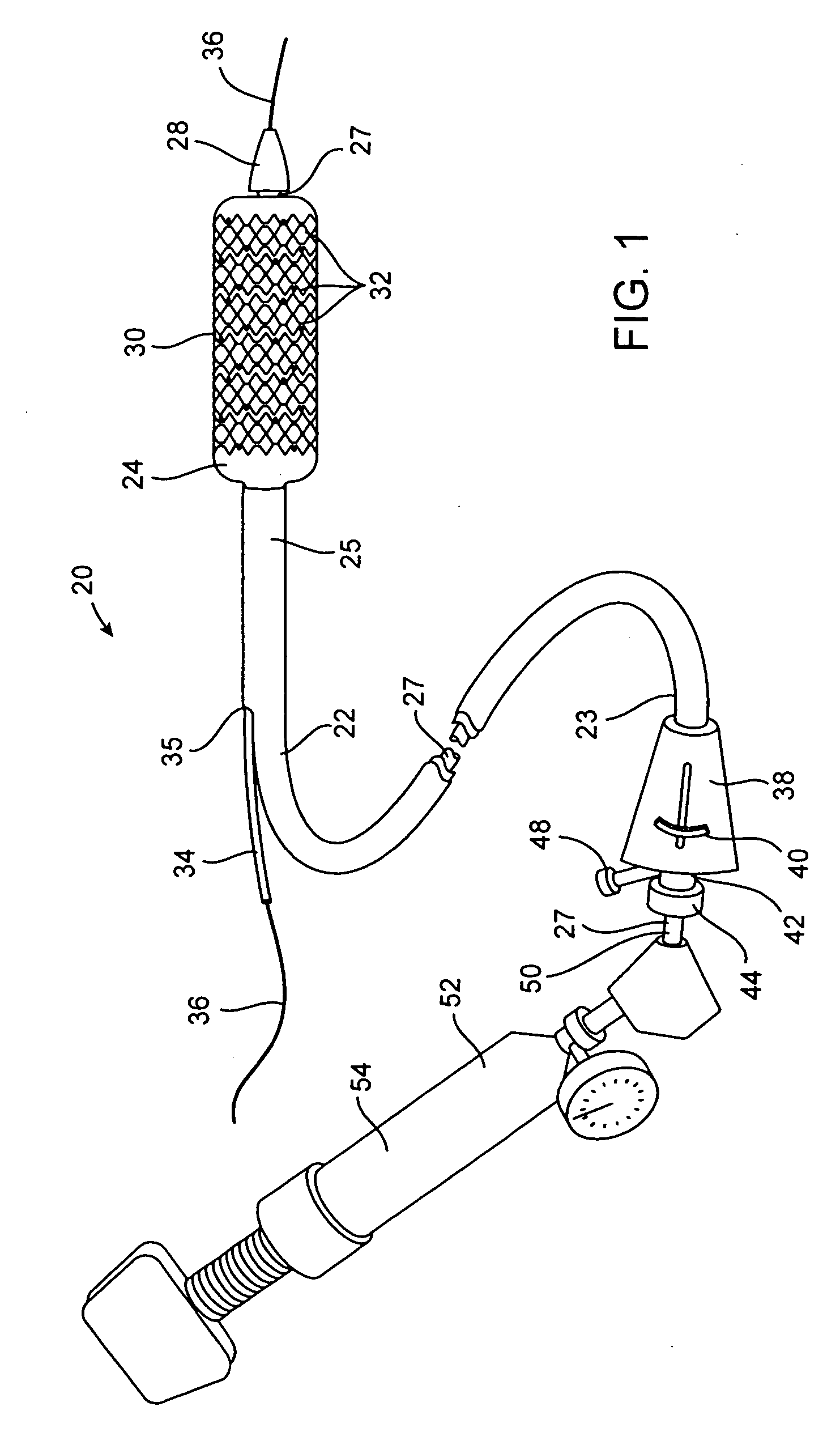
[0061] a stent delivery catheter according to present invention is illustrated in FIG. 1. Stent delivery catheter 20 includes a catheter body 22 comprising an outer sheath 25 slidably disposed over an inner shaft 27. An expandable member 24, preferably an inflatable balloon (shown in an inflated configuration), is mounted to inner shaft 27 and is exposed by retracting sheath 25 relative to inner shaft 27. A tapered nosecone 28, composed of a soft elastomeric material to reduce trauma to the vessel during advancement of the device, is mounted distally of expandable member 38. A stent 30, which preferably comprises a plurality of separate or separable stent segments 32, is disposed on expandable member 24 for expansion therewith. A guidewire tube 34 is slidably positioned through a guidewire tube exit port 35 in sheath 25 proximal to expandable member 24. A guidewire 36 is positioned slidably through guidewire tube 34, expandable member 24, and nosecone 28 and extends distally thereof...

second embodiment

[0119]FIGS. 6A-6B illustrate a stent segment 32 according to the invention. In FIG. 6A, a portion of stent segment 32 is shown in a planar shape for clarity. Similar to the embodiment of FIG. 5A, stent segment 32 comprises two parallel rows 122A, 122B of I-shaped cells 124 formed into a cylindrical shape around axial axis A. Cells 124 have upper and lower axial slots 126 and a connecting circumferential slot 128. Upper and lower slots 126 are bounded by upper axial struts 130, lower axial struts 132, curved outer ends 134, and curved inner ends 136. Circumferential slots 128 are bounded by outer circumferential strut 138 and inner circumferential strut 140. Each I-shaped cell 124 is connected to the adjacent I-shaped cell 124 in the same row 122 by a circumferential connecting strut 142. Row 122A is connected to row 122B by the merger or joining of curved inner ends 136 of at least one of upper and lower slots 126 in each cell 124.

[0120] One of the differences between the embodiment...


PUM


Abstract

Apparatus for delivering stents to body lumens include a flexible catheter shaft, an expandable member, a tubular prosthesis selectively movable in an axial direction over the expandable member, and a stop member disposed on the catheter shaft near the distal end of the catheter shaft for stopping the prosthesis at a deployment position on the expandable member. A variety of different stop members are provided according to various embodiments, such as stop members disposed outside the expandable member, stop members disposed inside the expandable member, movable stop members, and the like. Methods of delivering stents are also provided.

Description

CROSS-REFERENCES TO RELATED APPLICATIONS [0001] This application is a continuation-in-part of application Ser. No. ______, filed Jun. 22, 2004 (Attorney Docket No. 21629-000350US), which is a continuation-in-part of co-pending application Ser. No. 10 / 637,713, filed Jul. 21, 2003, which is a continuation-in-part of application Ser. No. 10 / 412,714, filed Apr. 10, 2003 (Attorney Docket No. 21629-000330), which is a continuation-in-part of application Ser. No. 10 / 306,813, filed Nov. 27, 2002 (Attorney Docket No. 21629-000320), which is a non-provisional of provisional application Ser. No. 60 / 336,767, filed Dec. 3, 2001 (Attorney Docket No. 21629-000300), and a non-provisional of provisional application Ser. No. 60 / 364,389, filed Mar. 13, 2002 (Attorney Docket No. 21629-000310), the disclosures of which are incorporated herein by reference.FIELD OF THE INVENTION [0002] This invention relates generally to vascular catheters, and more specifically to stents and stent delivery catheters for...

Claims


Application Information

Patent Timeline
Patent Type & Authority Applications(United States)
IPC IPC(8): A61F2/82
CPCA61F2/91A61F2/915A61F2/958A61F2002/826A61F2002/91508A61F2230/0013A61F2002/91525A61F2002/91533A61F2002/9155A61F2002/91558A61F2002/9583A61F2002/91516
Inventor ACOSTA, PABLOANDREAS, BERNARDKAO, STEPHENKARRATT, JOELANDREVILLE, STEVELANG, ERICSANDERSON, DAVIDWELK, CRAIGSNOW, DAVID
Owner JW MEDICAL SYSTEMS LTD
Learn More