

Facilities control system and method of controlling facilities
a technology of facilities and control systems, applied in the field of facilities control systems and control methods, can solve the problems of inability to predict a future situation, inability to carry out simulation, and inability to automatically cooperate with subsystems, etc., and achieve the effect of efficient operation
- Summary
- Abstract
- Description
- Claims
- Application Information
AI Technical Summary
Benefits of technology
Problems solved by technology
Method used
Image

Examples
first embodiment
[0058] [First Embodiment]
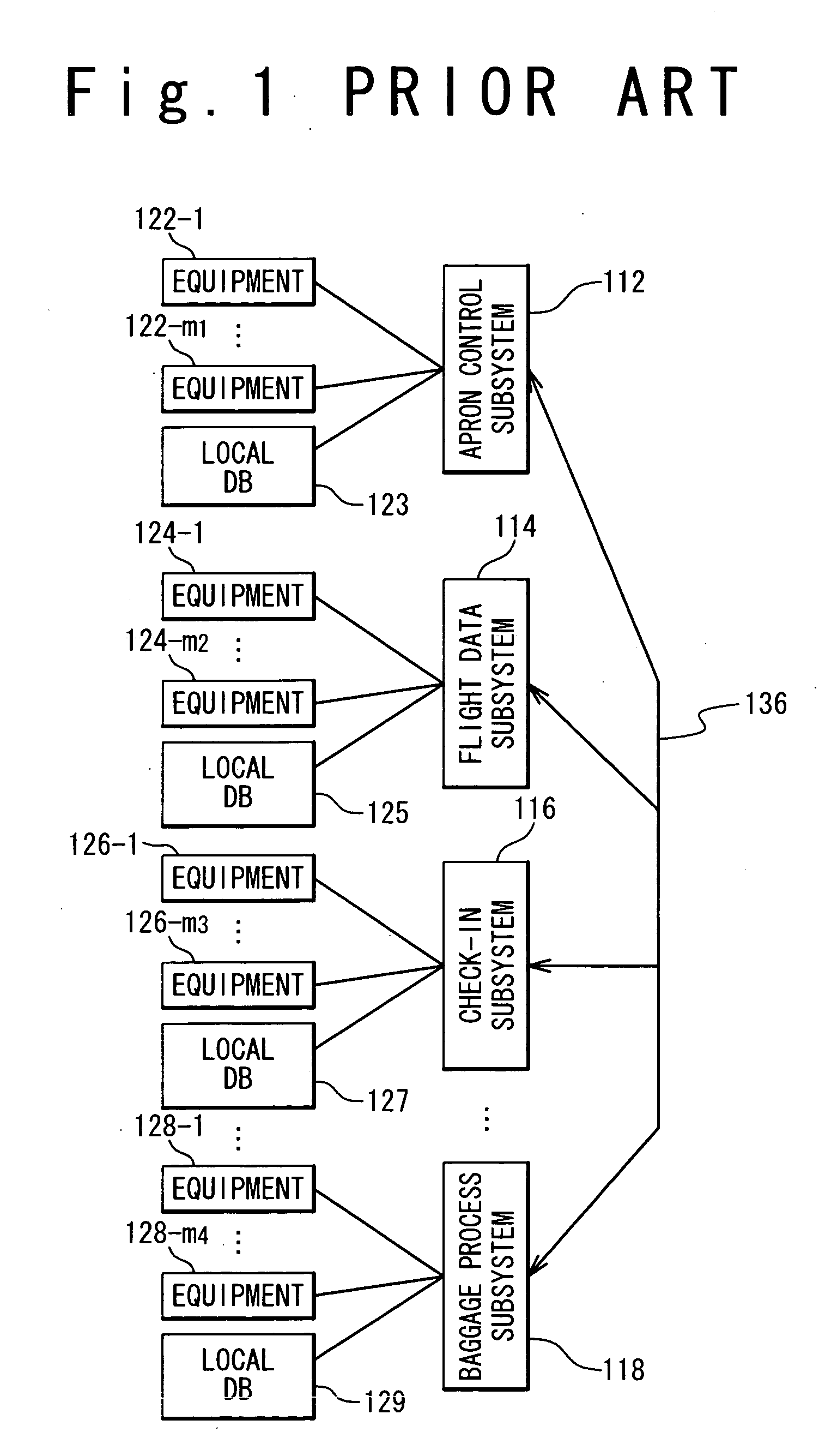
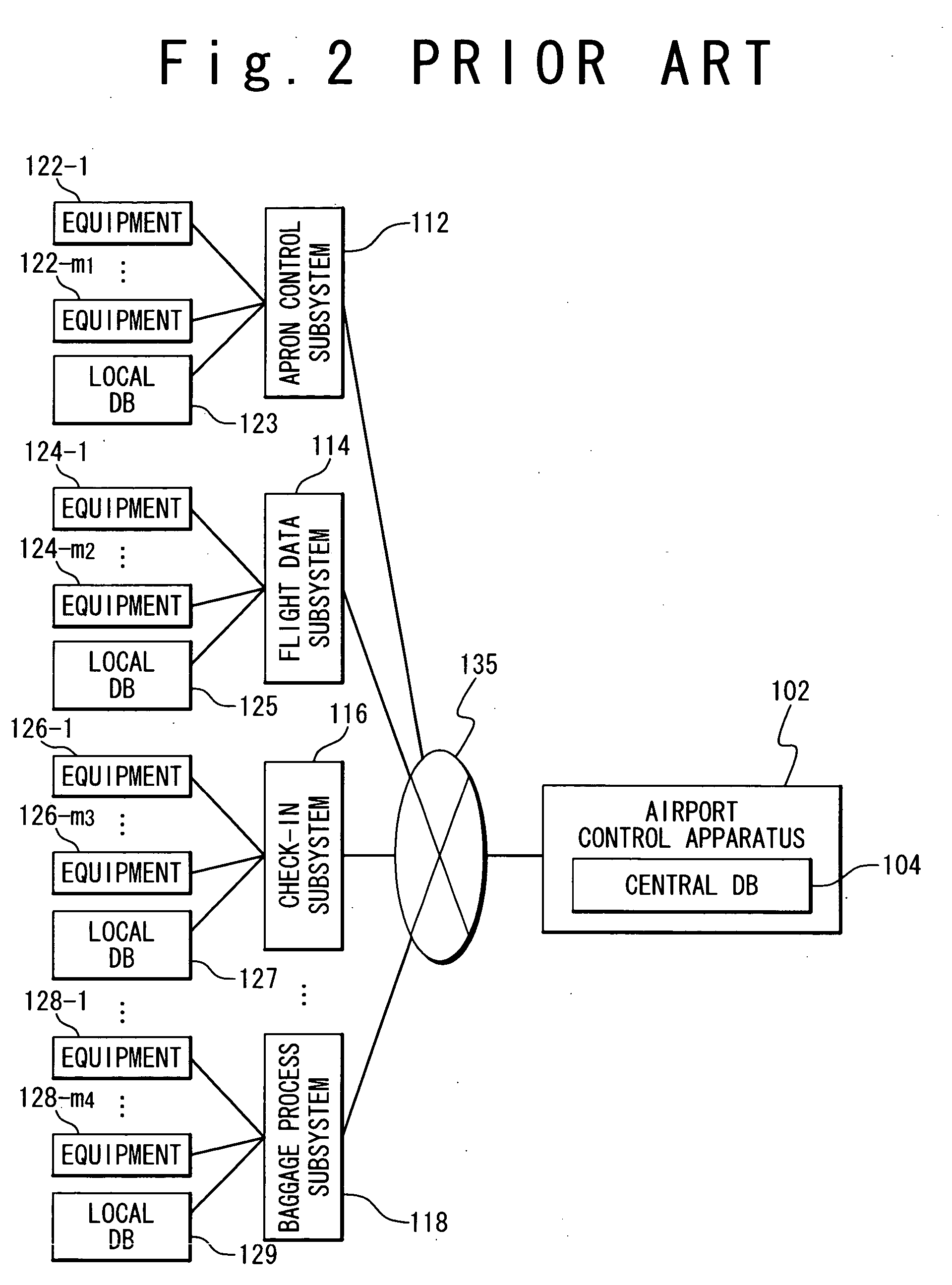
[0059] First, the facilities control system according to the first embodiment of the present invention will be described. FIG. 3 is a block diagram showing the configuration of an airport control system as the facilities control system according to the first embodiment of the present invention. The airport control system 1 is composed of an airport control apparatus 2, an airport simulation apparatus 6, and a display unit 11. The display unit 11 displays data supplied from the airport control apparatus 2 and the airport simulation apparatus 6. The airport control system 1 is connected with a plurality of subsystems 12 to 20 through a network 35. The subsystems 12 to 18 are same as the subsystems 112 to 118 shown in FIG. 2. In the present invention, a security control subsystem 20 is further provided and is composed of equipments 30-1 to 30-m5 and a local database 31. The network 35 is a network in the airport but the airport control system 1 can use data rec...
second embodiment
[0098] [Second Embodiment]
[0099] The facilities control system according to the second embodiment of the present invention will be described below. FIG. 3 is a block diagram showing the configuration of the facilities control system according to the second embodiment of the present invention. Because the airport control system 1 is the same as in the first embodiment, the description of the airport control system 1 will be omitted.
[0100]FIG. 15 is a block diagram showing another example of the model of the airport ground facilities. In the model of FIG. 15, processes are modeled that the passengers get off the arrived airplane and get on transportations through the arrival gate. Such a model is stored in the simulation model database 8e of the airport simulation apparatus 6. This model is set based on the arrangement of each process and each equipment in an actual airport. However, it is possible to set it virtually. The movement of the passengers from the arrived airplane can be s...
third embodiment
[0105] [Third Embodiment]
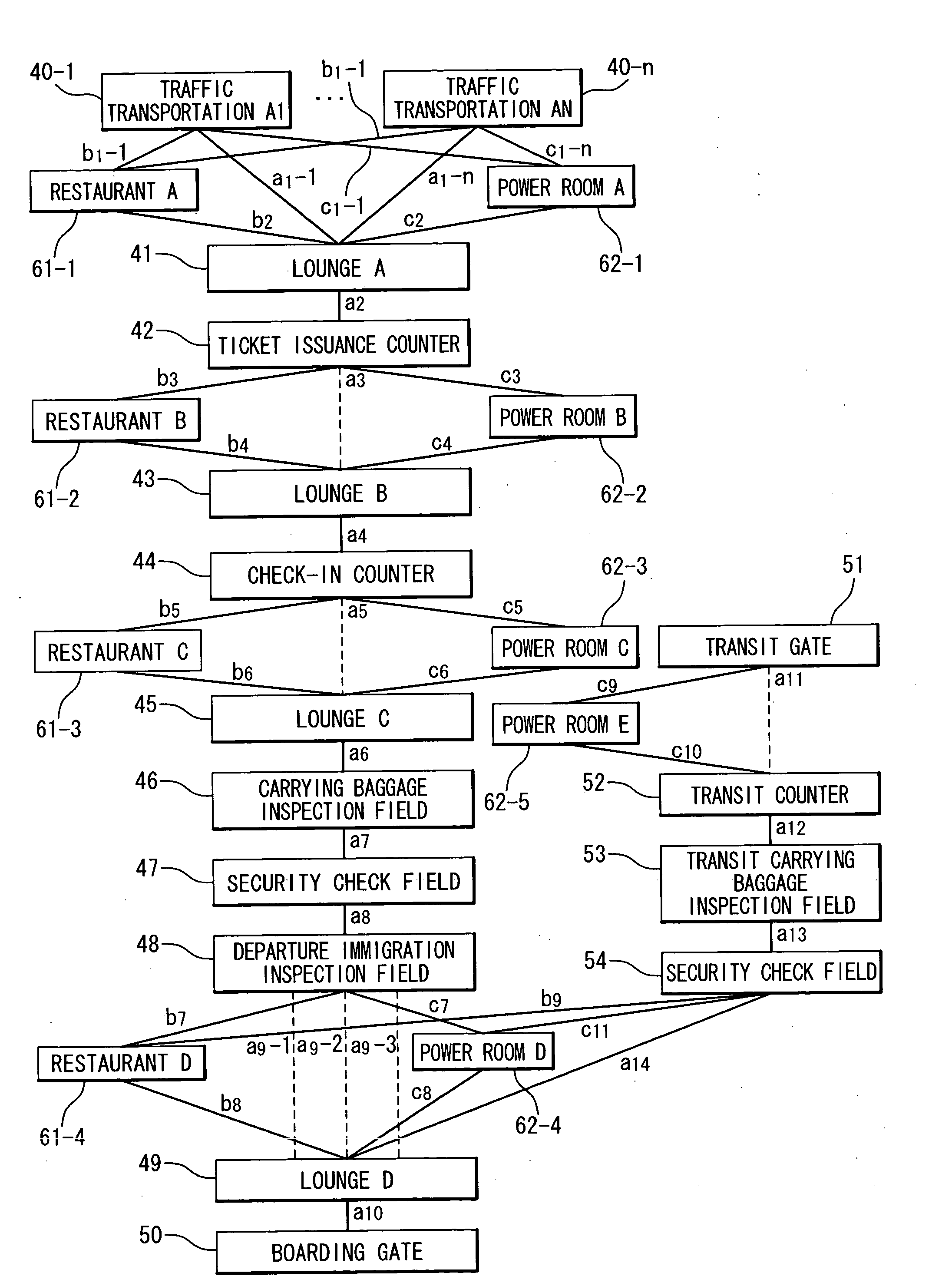
[0106] The facilities control system according to the third embodiment of the present invention will be described below. FIG. 3 is a block diagram showing the configuration of the facilities control system according to the third embodiment of the present invention. Because the airport control system 1 is the same as that of the first embodiment, the description is omitted. FIG. 13 is a block diagram showing an example of the model of the airport ground facilities. Because this airport model is the same as that of the first embodiment, the description is omitted.
[0107] Next, an operation of the facilities control system according to the third embodiment of the present invention will be described below. FIG. 16 is a flow chart showing the operation of the facilities control system according to the third embodiment of the present invention. A simulation and proposal of a measurement will be described when the airport model of FIG. 13 corresponds to an actual a...
PUM
 Abstract
Description
Claims
Application Information