Differential pressure sensor

a pressure sensor and differential technology, applied in the field of differential pressure sensors, can solve problems such as unsuitable measuremen

Active Publication Date: 2005-01-20
GRUNDFOS
View PDF5 Cites 12 Cited by
  • Summary
  • Abstract
  • Description
  • Claims
  • Application Information

AI Technical Summary

Benefits of technology

The measurement range or the measurement accuracy of the differential pressure sensor according to the invention, in particular with regard to the d

Problems solved by technology

The sensor known from DE 197 01 055 A1 as well as from EP 0 083 496 B1 may be applied as a differential pressure sensor, but however in practice is provided for a pressure

Method used


Image

  • Differential pressure sensor
  • Differential pressure sensor
  • Differential pressure sensor

Examples


Embodiment Construction

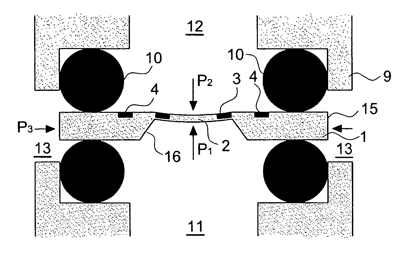
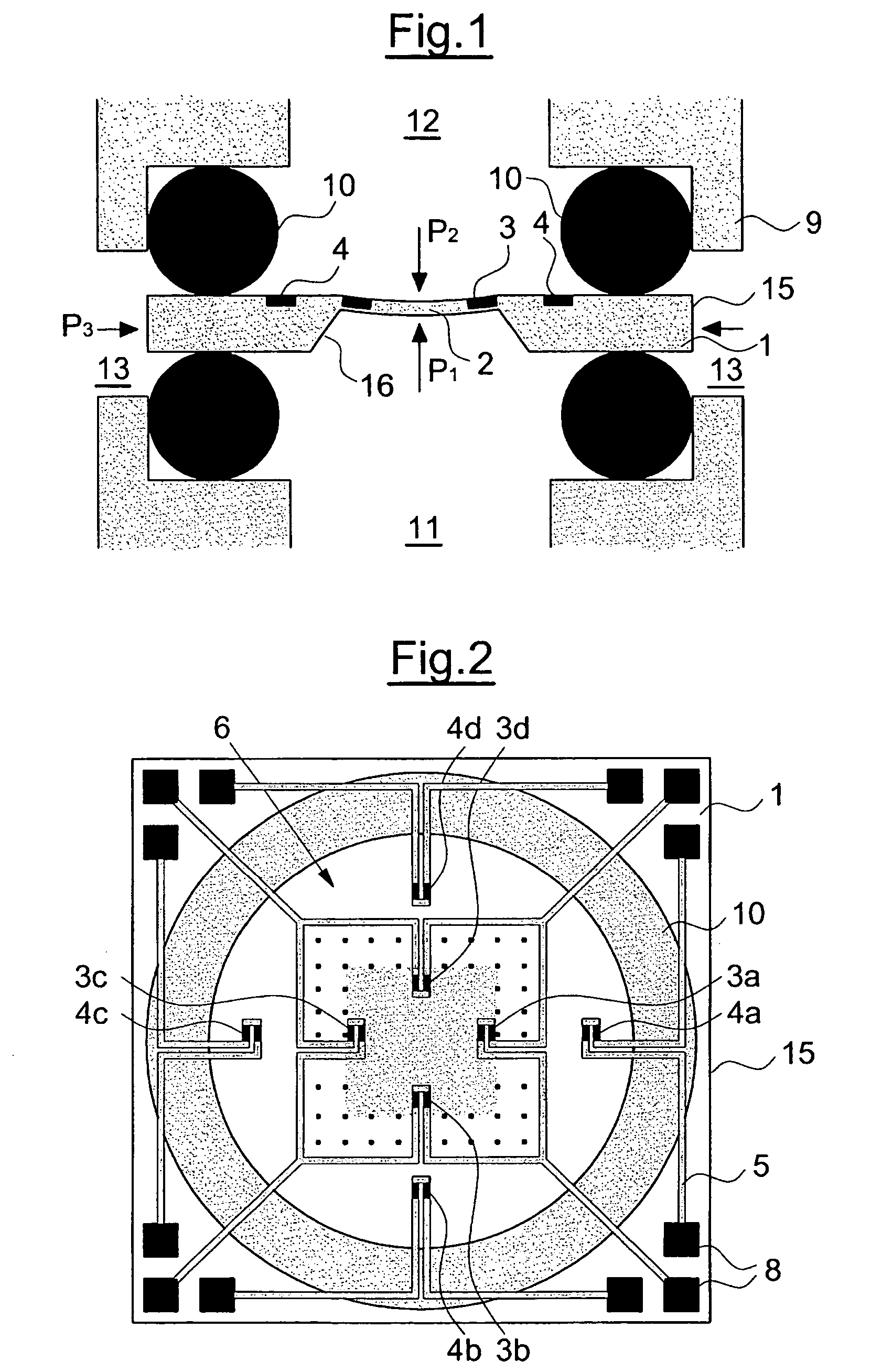
Referring to the drawings in particular, a differential pressure sensor as represented in FIGS. 1 and 2 is comprised of an essentially two-dimensionally formed semiconductor substrate 1 which in a middle region on the one side is thinned out into a membrane 2. Four measurement resistances 3a to 3d are formed in the known manner in the region of the membrane 2. Four further resistances in the form of compensation resistances 4a to 4d are formed directly next to the membrane 2 on the same side of the substrate. The arrangement of the resistances 3, 4 on the substrate 1 is to be deduced in detail from FIG. 2. Accordingly, the resistances 3, 4 are in each case arranged in a cross-like manner, wherein a compensation resistance 4 is allocated to each measurement resistance 3, and the compensation resistance runs in a direction parallel to the measurement resistance. The measurement resistances 1 are arranged directed parallel to one another as indeed are the compensation resistances 4, i...


PUM


Abstract

The differential pressure sensor is formed of a semiconductor substrate (1) which is thinned out in an inner region into a membrane (2) which may be impinged by pressure on both sides. Measurement resistances (3a to 3d) for detecting the differential pressure (P1 minus P2) are formed within the membrane (2), and compensation resistances (4) are formed on the carrier, which are connected to measurement resistances (3). The measurement resistances (3) are connected into a first measurement bridge (6) and the compensation resistances (4a to 4d) into a second measurement bridge (7).

Description

FIELD OF THE INVENTION The invention relates to a differential pressure sensor with a carrier which in an inner region comprises a membrane which may be acted on pressure on both sides, wherein measurement resistances for detecting the differential pressure acting on the membrane are formed within the membrane. BACKGROUND OF THE INVENTION Such differential pressure sensors are counted as belonging to the state of the art and are formed of a semiconductor substrate which in an inner region is thinned out into a membrane. Four measurement resistances are formed in this inner region, which are connected into a measurement bridge so that on deformation of the membrane, as occurs when impinged by pressure, the pressure acting on both sides of the membrane may be determined in the form of a differential pressure whilst making use of the piezoresistive effect. Differential pressure sensors as well as simple pressure sensors with which atmospheric pressure prevails on one side function ac...

Claims


Application Information

Patent Timeline
IPC IPC(8): G01L13/02G01L19/04
CPCG01L9/065G01L13/025
Inventor KROG, JENS PETERPEDERSEN, CASPERCHRISTENSEN, CARSTEN
Owner GRUNDFOS
Why Eureka
Try Eureka