Doppler ultrasonic flowmeter

a flowmeter and ultrasonic technology, applied in the direction of liquid/fluent solid measurement, instruments, machines/engines, etc., can solve the problems of time, cost and labor, and the validity of measurement results may be damaged, and achieve the effect of high accuracy, simple, easy, and high versatility

Inactive Publication Date: 2005-01-20
TAKEDA KK +1
View PDF3 Cites 22 Cited by
  • Summary
  • Abstract
  • Description
  • Claims
  • Application Information

AI Technical Summary

Benefits of technology

As described above, the Doppler type ultrasonic flowmeter according to the present invention is provided with the frequency selecting and setting means for automatically selecting and setting oscillation frequencies of ultrasonic pulses emitted from an ultrasonic transducer, and the incident angle adjusting and setting means for selectably setting the incident angles of ultrasonic pulses emitted from the ultrasonic transducer to optimum angles. According to this arrangement, it is possible to automatically set optimum frequencies or optimum incident angles of ultrasonic waves that cause the resonant transmission phenomenon to take place with respect to the wall thickness of a fluid pipe. This obviates the need for provi

Problems solved by technology

Strictly speaking, this theoretical solution applies to a flow in a steady state, and therefore, the ultrasonic flowmeter based on the approximate integration can be applied only to a flow of a steady state and cannot be used for the flow in non-steady state.
For this reason, if an object to be measured is a flow field (the flow field of a fluid) where the approximate integration does not hold due to time-dependent changes in the flow rate, then measurement accuracy may be significantly deteriorated or validity of measurement results may be damaged.
This requires time, cost and labor to provide piping.
In addition, since the flowmeters are for measuring flow rates of flows in steady states, it has been difficult to measure flow rates of flows in non-steady states.
Furthermore, the conventional flowmeters are adapted to measure an average flow rate of a fluid passi

Method used


Image

  • Doppler ultrasonic flowmeter
  • Doppler ultrasonic flowmeter
  • Doppler ultrasonic flowmeter

Examples


second embodiment

FIG. 5 shows the Doppler type ultrasonic flowmeter in accordance with the present invention.

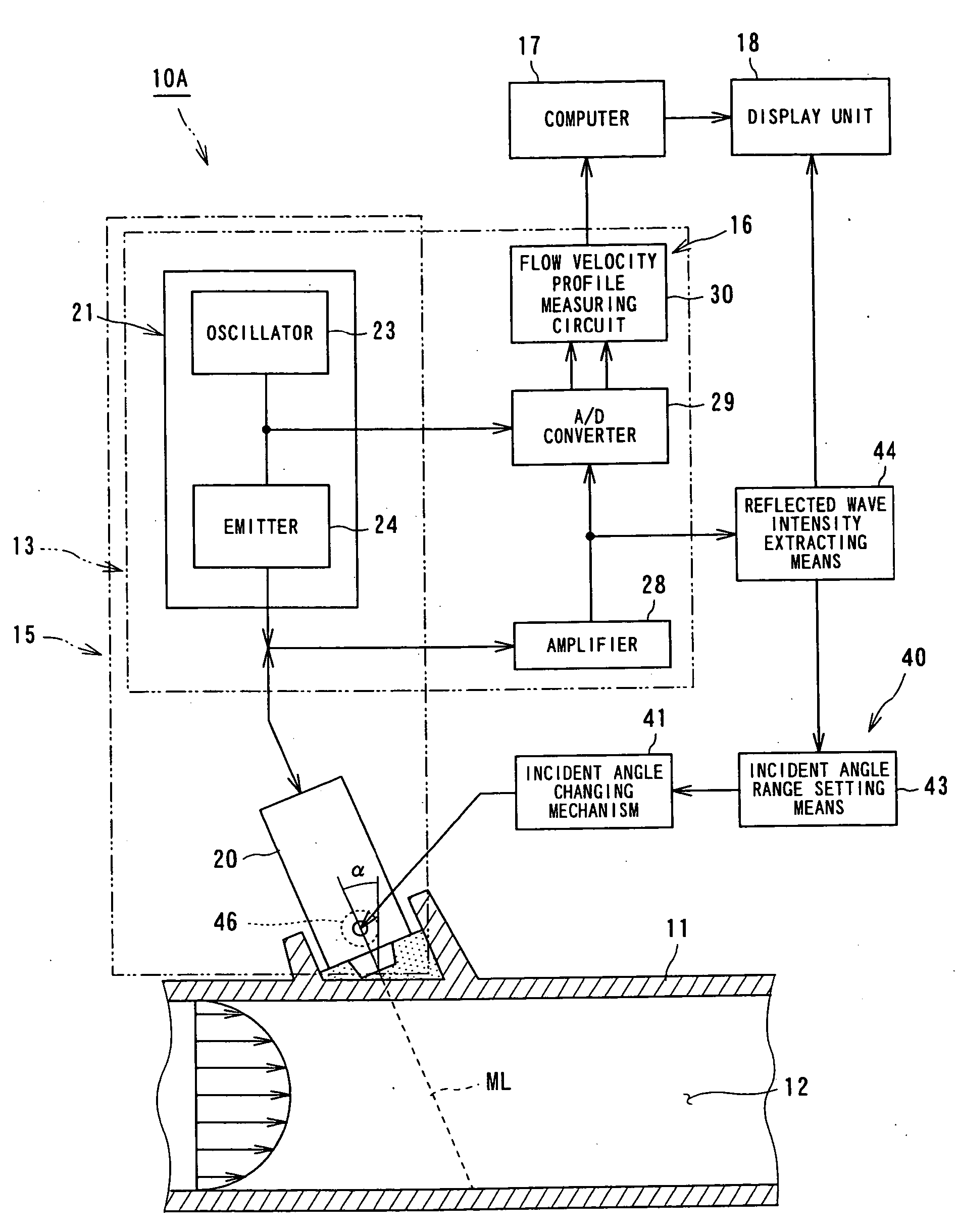
A Doppler type ultrasonic flowmeter 10A shown in this embodiment may be adapted to change the wall thickness of a fluid pipe 11 to induce the resonant transmission phenomenon as a method to improve the S / N ratio of reflected waves in place of selecting an optimum frequency of an ultrasonic pulse entering the fluid pipe 11.

However, since it is actually impossible to change the wall thickness of the fluid pipe 11, a means equivalent to changing the wall thickness of the fluid pipe 11 has been provided by changing the mounting angle of an ultrasonic transducer 20.

In the second embodiment, an incident angle α of the ultrasonic pulses emitted from the ultrasonic transducer 20 is adjusted and set by an incident angle adjusting and setting means 40 thereby to automatically select the incident angle of an ultrasonic wave which corresponds to the wall thickness of the fluid pipe 11. The like refe...

third embodiment

FIG. 6 to FIG. 8 show the Doppler type ultrasonic flowmeter in accordance with the present invention.

As illustrated in FIG. 6, a Doppler type ultrasonic flowmeter 10B of this embodiment calculates, on the basis of a Doppler frequency, a velocity component V2 in the direction of an ultrasonic wave incident angle (entering angle) of a fluid 12 to be measured which is flowing in a fluid pipe 11. From the calculated Doppler frequency, the flow velocity profile along a measurement line ML is determined according to a linear measurement method so as to calculate the flow rate of the fluid 12.

The Doppler type ultrasonic flowmeter 10B calculates the velocity vector V2 in the direction of an ultrasonic path (the measurement line ML) from the Doppler frequency and divides the velocity vector V2 by sin α so as to calculate the velocity vector V1 in the axial direction of the fluid pipe 11.

The Doppler type ultrasonic flowmeter 10B cannot calculate correct flow velocities if the flow of the...


PUM


Abstract

A Doppler type ultrasonic flowmeter has an ultrasonic transmitting means for emitting ultrasonic pulses from an ultrasonic transducer into a fluid pipe, a flow velocity profile measuring means for receiving an ultrasonic echo reflected from a measurement region in the fluid pipe thereby to measure a flow velocity profile of a fluid to be measured, a fluid flow rate computing means for calculating the flow rate thereof on the basis of the flow velocity profile of the fluid to be measured, and a frequency selecting and setting means for automatically selecting a fundamental frequency of an ultrasonic wave that causes a resonant transmission phenomenon to take place from the ultrasonic transducer. The frequency selecting and setting means controls the operation of the ultrasonic transmitting means such that an ultrasonic wave of a selected optimum frequency is emitted from the ultrasonic transducer. This arrangement makes it possible to provide a highly versatile Doppler type ultrasonic flowmeter that permits simple, easy, contactless, precise and highly accurate measurement of the flow rates of fluids to be measured that are flowing in various fluid pipes.

Description

TECHNICAL FIELD The present invention relates to a Doppler type ultrasonic flowmeter for measuring a flow rate of a fluid to be measured by utilizing an ultrasonic Doppler shift and, more particularly, to a Doppler type ultrasonic flowmeter that permits automatic adjustment and setting of optimum frequencies and optimum incident angles of ultrasonic waves. BACKGROUND ART Flowmeters for measuring flow velocities and flow rates of fluids to be measured that are passing in fluid pipes are roughly divided into two types according to measurement principles. A first type of flowmeters measures flow rates by making use of the fact that the processing amount of a fluid flowing through a fluid pipe changes, depending upon flowing direction. As this type of flowmeter, there is an orifice flowmeter. The orifice flowmeter measures flow rates by utilizing the fact that fluid pressure on upstream side of an orifice differs from that on the downstream side. This flow rate measuring method will ...

Claims


Application Information

Patent Timeline
IPC IPC(8): G01F1/66
CPCG01F1/667G01F1/663G01F1/66
Inventor TAKEDA, YASUSHIMORI, MICHITSUGU
Owner TAKEDA KK
Why Eureka
Try Eureka