Supercharge Your Innovation With Domain-Expert AI Agents!

Crank structure of bicycle

Inactive Publication Date: 2005-01-20
CHIANG DOUGLAS
View PDF4 Cites 34 Cited by
  • Summary
  • Abstract
  • Description
  • Claims
  • Application Information

AI Technical Summary

Benefits of technology

[0006] The primary objective of the present invention is to provide a crank structure, wherein the main body and the crank shaft are made of aluminum alloy material having a greater structural strength, thereby enhancing the structural strength of the main body and the crank shaft of the L-shaped crank structure.
[0007] Another objective of the present invention is to provide a crank structure, wherein the main body is integrally formed with the wing plates, thereby enhancing the combination strength of the main body and the chain wheel.
[0008] A further objective of the present invention is to provide a crank structure, wherein the main body is integrally formed with the wing plates, without having to assemble the wing plates additionally, so that the crank structure can be assembled rapidly, easily and conveniently.
[0009] A further objective of the present invention is to provide a crank structure, wherein after the crank shaft is mounted on the main body in a close fit manner, the composite material layer is coated around the outer periphery of the main body, so that the main body and the crank shaft have an enhanced combination strength. Thus, the crank shaft mounted on the main body in a close fit manner will not detach from the main body during travel of the bicycle.
[0010] A further objective of the present invention is to provide a crank structure, wherein the crank shaft is mounted on the second mounting portion of the main body, and the composite material layer is then coated around the outer periphery of the main body, so that the composite material layer coated around the outer periphery of the main body will not be broken easily.
[0011] A further objective of the present invention is to provide a crank structure, wherein the crank structure is made of aluminum alloy material and carbon fiber material, so that the crank structure has an enhanced structural strength and has a light weight.

Problems solved by technology

However, the crank shaft is screwed onto the primary aluminum member of the main body, so that the crank shaft is easily detached from the main body during a long-term utilization.
In addition, the primary aluminum member and the secondary aluminum member of the main body are coated with the outer layer made of carbon fiber, so that when the crank shaft is screwed into the screw bore of the primary aluminum member of the main body, the outer layer made of carbon fiber is easily broken.

Method used


Image

  • Crank structure of bicycle
  • Crank structure of bicycle
  • Crank structure of bicycle

Examples


Embodiment Construction

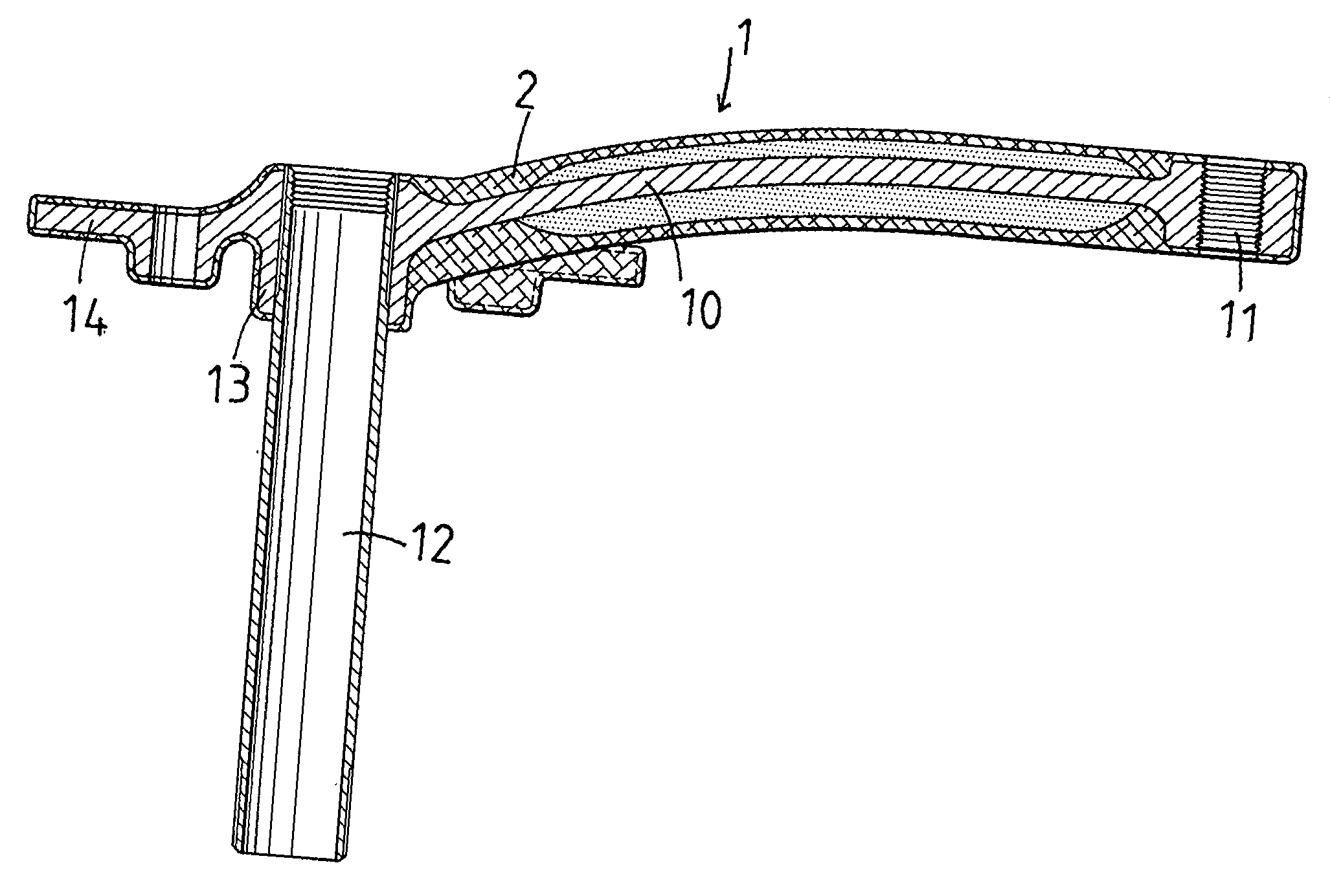
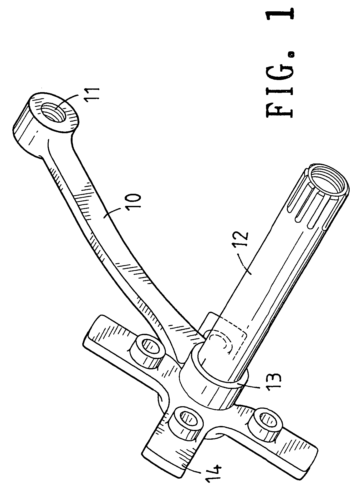
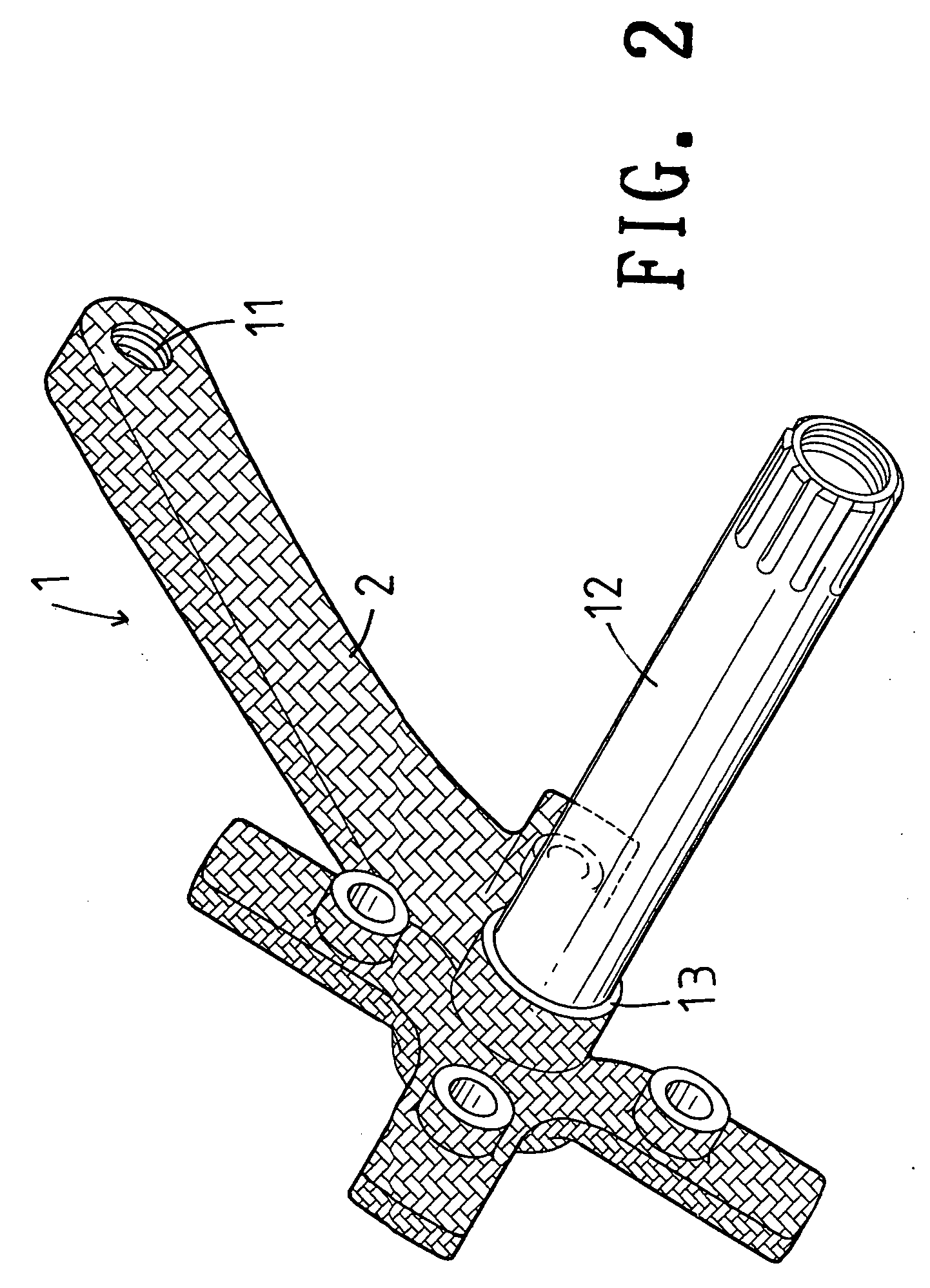
[0029] Referring to the drawings and initially to FIGS. 1-5, a crank structure 1 of a bicycle in accordance with the preferred embodiment of the present invention comprises a main body 10, and a crank shaft 12.

[0030] The main body 10 is made of aluminum alloy material and is formed by forging. The main body 10 has a first end provided with a first mounting portion 11 for connection to a pedal 30 (see FIG. 6), and a second end provided with a second mounting portion 13. The second mounting portion 13 of the main body 10 has a periphery provided with a plurality of protruding wing plates 14 for connection to a chain wheel 32 (see FIG. 6). Preferably, the second mounting portion 13 of the main body 10 is integrally formed with the wing plates 14.

[0031] The crank shaft 12 is a hollow body which is made of aluminum alloy material and is formed by forging. The crank shaft 12 is mounted on the second mounting portion 13 of the main body 10 in a close fit manner.

[0032] The crank structur...


PUM


Abstract

A crank structure includes a main body, a crank shaft, and a composite material layer. In assembly, after the crank shaft is mounted on the main body in a close fit manner, the composite material layer is coated around the outer periphery of the main body, so that the main body and the crank shaft have an enhanced combination strength. Thus, the crank shaft mounted on the main body in a close fit manner will not detach from the main body during travel of the bicycle.

Description

BACKGROUND OF THE INVENTION [0001] 1. Field of the Invention [0002] The present invention relates to a crank structure, and more particularly to a crank structure of a bicycle. [0003] 2. Description of the Related Art [0004] A conventional crank of a bicycle comprises a main body having a front end provided with a primary aluminum member and a rear end provided with a secondary aluminum member, an outer layer made of carbon fiber coated on the periphery of the primary aluminum member and the secondary aluminum member of the main body, a crank shaft screwed into the primary aluminum member of the main body, and a pedal screwed onto the secondary aluminum member of the main body. [0005] However, the crank shaft is screwed onto the primary aluminum member of the main body, so that the crank shaft is easily detached from the main body during a long-term utilization. In addition, the primary aluminum member and the secondary aluminum member of the main body are coated with the outer laye...

Claims


Application Information

Patent Timeline
IPC IPC(8): B62M3/00
CPCB62M3/00Y10T74/2164B62M3/003
Inventor CHIANG, DOUGLAS
Owner CHIANG DOUGLAS
Features
  • R&D
  • Intellectual Property
  • Life Sciences
  • Materials
  • Tech Scout
  • Unparalleled Data Quality
  • Higher Quality Content
  • 60% Fewer Hallucinations
Learn More