Gasification monitor, method for detecting mist, film forming method and film forming apparatus

a technology of gasification monitor and mist detection, which is applied in the direction of liquid surface applicators, chemical vapor deposition coatings, coatings, etc., can solve the problems of reducing the productivity of the deposition process, increasing the specificity of the deposition technique, and increasing the difficulty of detecting deposition defects. achieve the effect of preventing film forming defects

Inactive Publication Date: 2005-01-20
TOKYO ELECTRON LTD
View PDF2 Cites 19 Cited by
  • Summary
  • Abstract
  • Description
  • Claims
  • Application Information

AI Technical Summary

Benefits of technology

[0008] In the above-mentioned situation, it is an object of the present invention to provide a t...

Problems solved by technology

With high integration and high-density of semiconductor devices, the specifications of deposition technique are becoming increasingly severe every year.
In the MOCVD method mentioned above, there is a worry that if the evaporation of liquid material is incomplete in the vaporizer, the liquid material in the form of mist in a processing gas is transported the chamber, so that the liquid materials may adhere to a thin film on a substrate.
Nevertheless, the same publicati...

Method used


Image

  • Gasification monitor, method for detecting mist, film forming method and film forming apparatus
  • Gasification monitor, method for detecting mist, film forming method and film forming apparatus
  • Gasification monitor, method for detecting mist, film forming method and film forming apparatus

Examples


Embodiment Construction

[0033] An embodiment of the present invention will be described with reference to accompanying drawings.

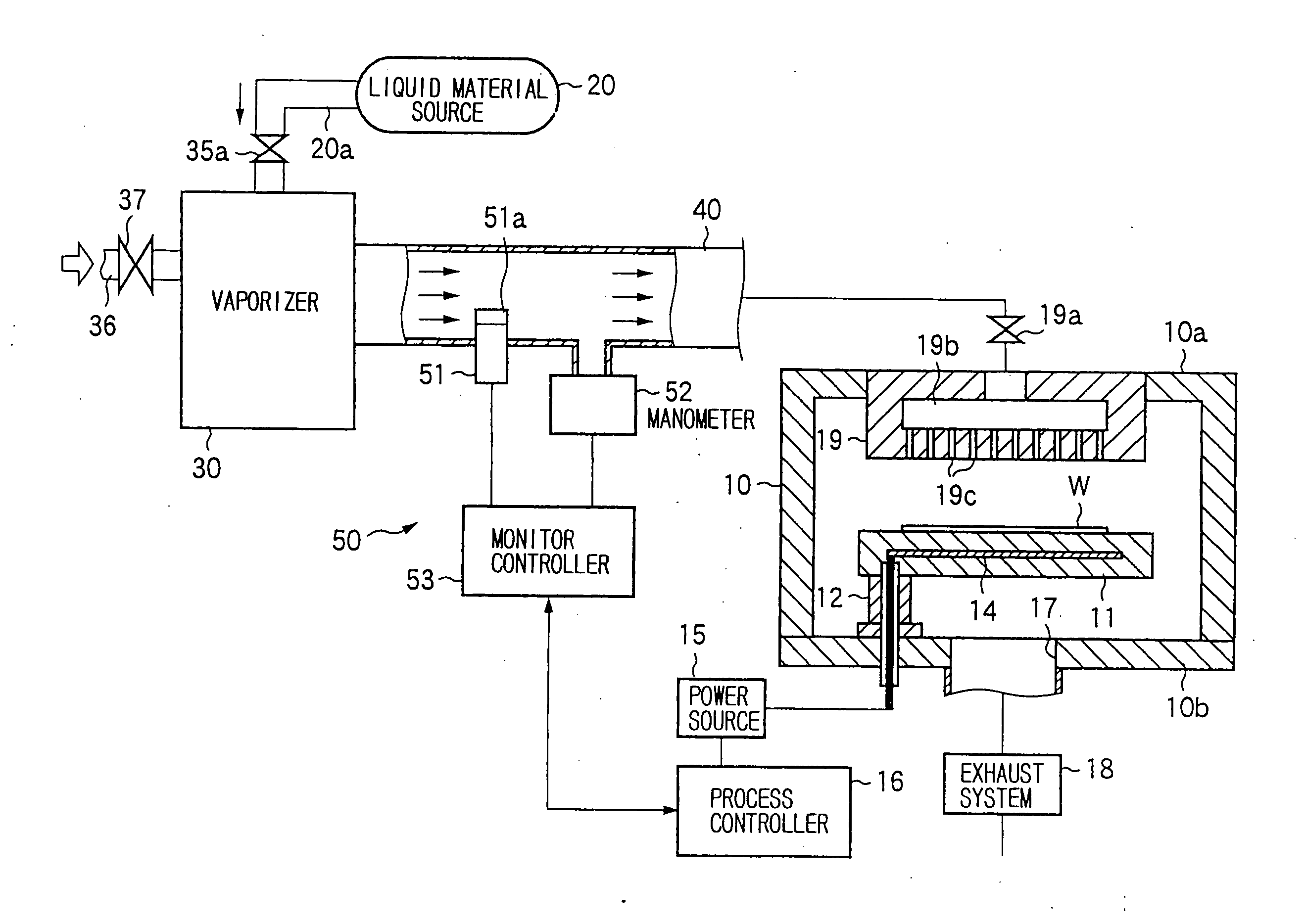
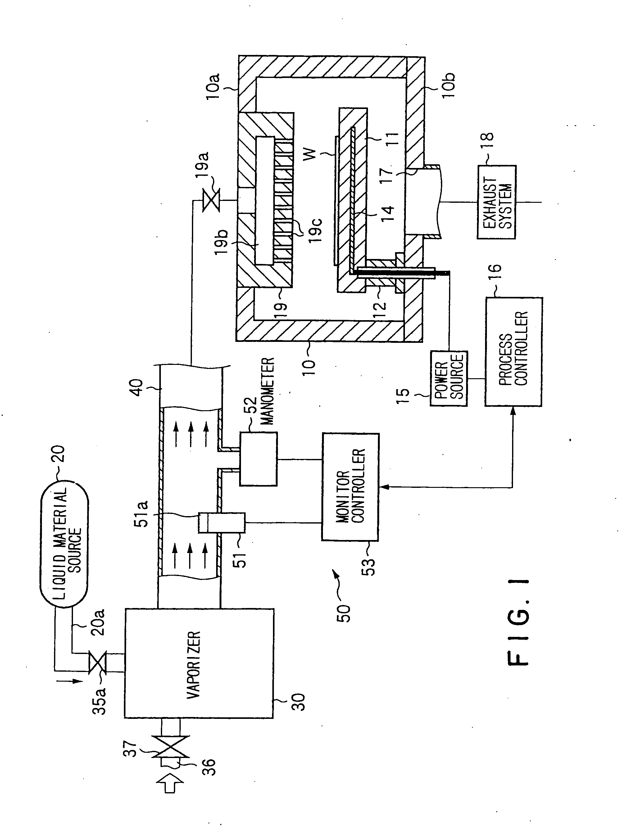
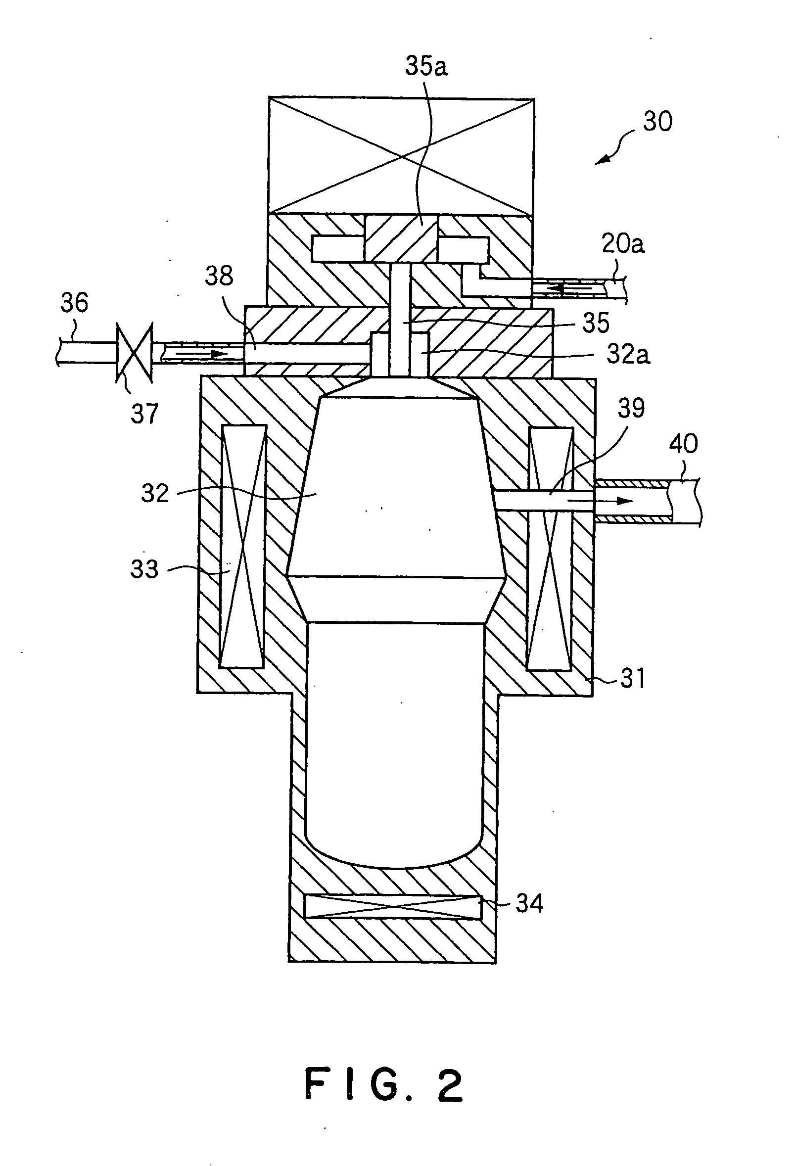
[0034]FIG. 1 illustrates a deposition apparatus for carrying out a deposition method in accordance with one embodiment of the present invention. By way of example, the deposition apparatus is provided to form a HF (hafnium) oxidation film by means of CVD (chemical vapor deposition). The deposition apparatus includes a chamber 10 forming a processing part of the apparatus, a liquid-material source 20 for supplying a liquid material containing HF, a vaporizer 30 for vaporizing the liquid material from liquid-material source 20 to produce a processing gas and a processing-gas pipe (gas feeding path) 40 for introducing the so-produced processing gas into the chamber 10.

[0035] The chamber 10 is cylindrical-shaped and constructed so as to allow its pumping to a vacuum. Disposed in the chamber 10 is a susceptor 11 that supports a semiconductor wafer W as an object to be processed, hori...


PUM

PropertyMeasurementUnit
Pressureaaaaaaaaaa
Metallic bondaaaaaaaaaa
Threshold limitaaaaaaaaaa

Abstract

A deposition apparatus supplies a reactive gas obtained by vaporizing a liquid material at a vaporizer 30 into a chamber 10 via a processing-gas pipe 40 and forms a thin film on a semiconductor wafer W due to a thermal decomposition of the reactive gas. The deposition apparatus is provided, in the processing-gas pipe 40, with a crystal gauge 51 detecting a pressure Pq under the influence of mist in the reactive gas and a capacitance manometer 52 detecting a pressure Pg under no influence of the mist. The apparatus further includes a gasification monitor 50 detecting a quantity of mist in the reactive gas on the basis of a difference ΔP between the pressure Pq and the pressure Pg measured by the crystal gauge 51 and the capacitance manometer 52 in order to prevent deposition defects due to the mist in the reactive gas.

Description

BACKGROUND OF THE INVENTION [0001] 1. Field of the Invention [0002] This invention relates to a gasification monitor, a method for detecting mist, a film forming method and a film forming apparatus, which are applicable to a technique where, for example, a liquid material or a solid material is vaporized and supplied into a chamber to perform a designated processing, such as chemical vapor deposition (CVD). [0003] 2. Background Art [0004] In order to manufacture a desired semiconductor device, generally, there are repeatedly carried out a film deposition process and a pattern etching process against a semiconductor wafer. With high integration and high-density of semiconductor devices, the specifications of deposition technique are becoming increasingly severe every year. For instance, even for an oxidation film of great thinness (e.g. insulation film, gate insulation film, etc. of a capacitor in a device), an electrode film and a wiring film, it is required to reduce the film-thick...

Claims


Application Information

Patent Timeline
IPC IPC(8): C23C16/00C23C16/448C23C16/52H01L21/31
CPCC23C16/52C23C16/4481
Inventor IWATA, TERUO
Owner TOKYO ELECTRON LTD
Why Eureka
Try Eureka