
Sputtering apparatus

Inactive Publication Date: 2005-01-20
PANASONIC CORP
View PDF19 Cites 11 Cited by
  • Summary
  • Abstract
  • Description
  • Claims
  • Application Information

AI Technical Summary

Benefits of technology

[0023] In this configuration, since reaction plasma formed of after-glow plasma can be produced in the vicinity of the substrate holder, it is possible to form compound film being close to bulk characteristics and free from damage by plasma at a relatively low substrate temperature.

Problems solved by technology

Further, since substrate 5 is heated by plasma, there is a problem that the thin film cannot be formed at a desired temperature of the substrate.
However, when such a plasma source is used as a plasma source for reaction shown in FIG. 4, there are problems as mentioned in the following.
As a result, arc discharge is generated at the surface of the target during sputtering operation, and there may arise generation of unstable sputtering and also splash in the thin film formed.

Method used


Image

  • Sputtering apparatus
  • Sputtering apparatus
  • Sputtering apparatus

Examples


Embodiment Construction

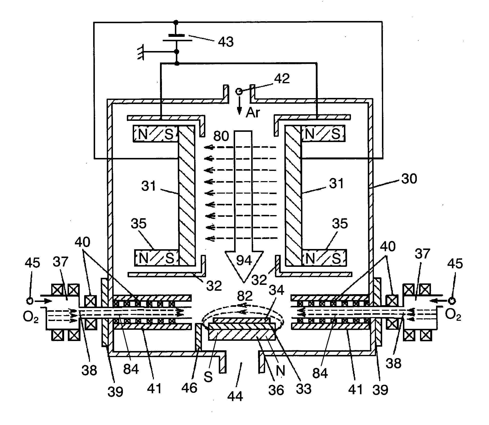
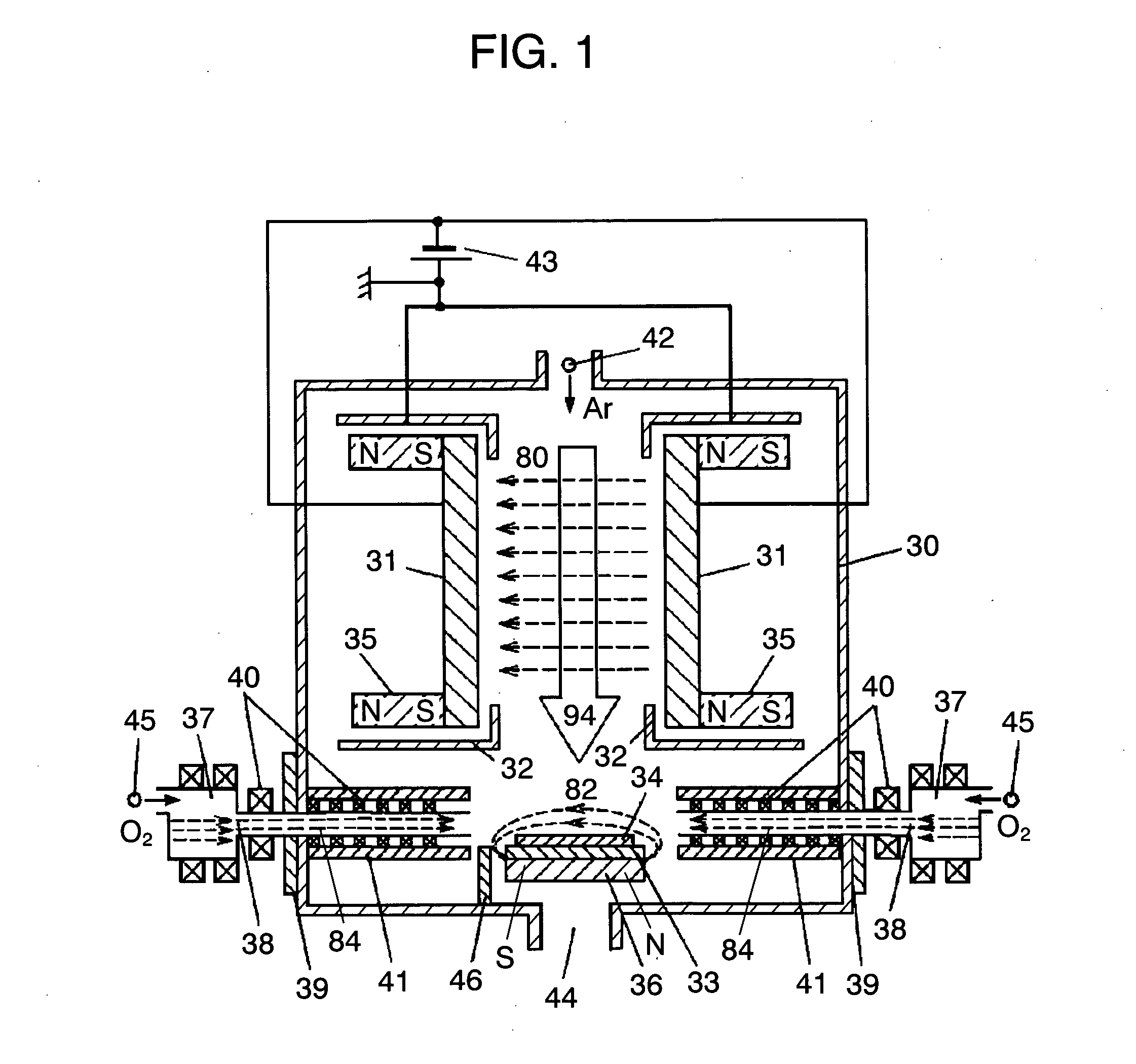
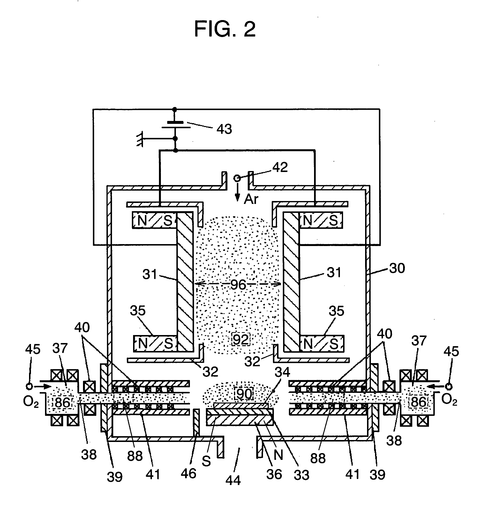
[0029] The whole configuration of a facing-targets sputtering apparatus related to the exemplary embodiment of the present invention will be described in the following with reference to FIG. 1 to FIG. 3B.

[0030]FIG. 1 is a sectional outline drawing showing the configuration of a sputtering apparatus of the present invention. FIG. 2 is an explanatory drawing showing a plasma distribution formed by the sputtering apparatus of the present invention. FIG. 3A and FIG. 3B are sectional outline drawings showing the branch structure of the tip portion of a lead-in pipe used in the sputtering apparatus of the present invention.

[0031] In FIG. 1 and FIG. 2, paired targets 31 are disposed in vacuum chamber 30, which are spaced apart, opposed and nearly parallel to each other. Substrate holder 33 is disposed at a position apart from a space formed by the surfaces of paired targets 31. The distance between paired targets 31 is in a range from about 100 mm to 180 mm, and the distance from substra...


PUM

PropertyMeasurementUnit
Temperatureaaaaaaaaaa
Magnetic fieldaaaaaaaaaa
Soft magnetismaaaaaaaaaa

Abstract

It comprises paired targets 31 disposed in vacuum chamber 30, substrate holder 33 disposed at a position nearly perpendicular to the paired target 31 and apart from a space formed by the paired targets 31, plasma source 37 for generating reaction plasma by after-glow plasma in the vicinity of the substrate holder 33, and lead-in pipe 38 which connects the plasma source 37 to the vacuum chamber 30. Since reaction plasma of after-glow plasma can be produced in the vicinity of the substrate holder 33, it is possible to form a thin film of compound close to bulk characteristics at a low substrate temperature without being damaged by plasma.

Description

FIELD OF THE INVENTION [0001] The present invention relates to a sputtering apparatus, and more particularly, it relates to a facing-targets sputtering apparatus which forms a thin film through reactive sputtering process. BACKGROUND OF THE INVENTION [0002] A method of manufacturing reactive sputtered thin film by using a conventional facing-targets sputtering apparatus is disclosed in Japanese Laid-open Patent H2-38310. The method disclosed in this example is such that oxygen plasma is locally generated on the upper surface of a substrate, then oxidation reaction occurs against particles sputtered from the target, thereby manufacturing oxide superconductor film. FIG. 4 is a sectional outline drawing showing the configuration of an essential portion of a conventional opposed-target sputtering apparatus. [0003] In FIG. 4, paired targets 4 are oppositely disposed at a spaced interval. At the backs of these targets 4 are respectively disposed magnets 3 for forming a magnetic field betw...

Claims


Application Information

Patent Timeline
IPC IPC(8): C23C14/00C23C14/34C23C14/35H01J37/32H01J37/34H01L21/31
CPCC23C14/0047C23C14/228H01J37/3402H01J37/32C23C14/352
Inventor NODA, TOSHINARI
Owner PANASONIC CORP
Learn More