Noise dampening degaussing coil holder

a degaussing coil and coil holder technology, applied in the direction of electromagnetic effect elimination, electric discharge tubes, instruments, etc., can solve the problems of user distraction, heat shrink bands may also become magnetized, etc., and achieve the effect of dampening noise transmission

Inactive Publication Date: 2005-01-20
SONY CORP +1
View PDF12 Cites 1 Cited by
  • Summary
  • Abstract
  • Description
  • Claims
  • Application Information

AI Technical Summary

Benefits of technology

[0006] A system includes a cathode ray tube (CRT) and at least one degaussing coil juxtaposed with the CRT. A resilient cylindrical d

Problems solved by technology

In addition, heat shrink bands may also become magnetized.
As recognized herein, however, while effective for their intended purpose, degaussing c

Method used


Image

  • Noise dampening degaussing coil holder
  • Noise dampening degaussing coil holder

Examples


Embodiment Construction

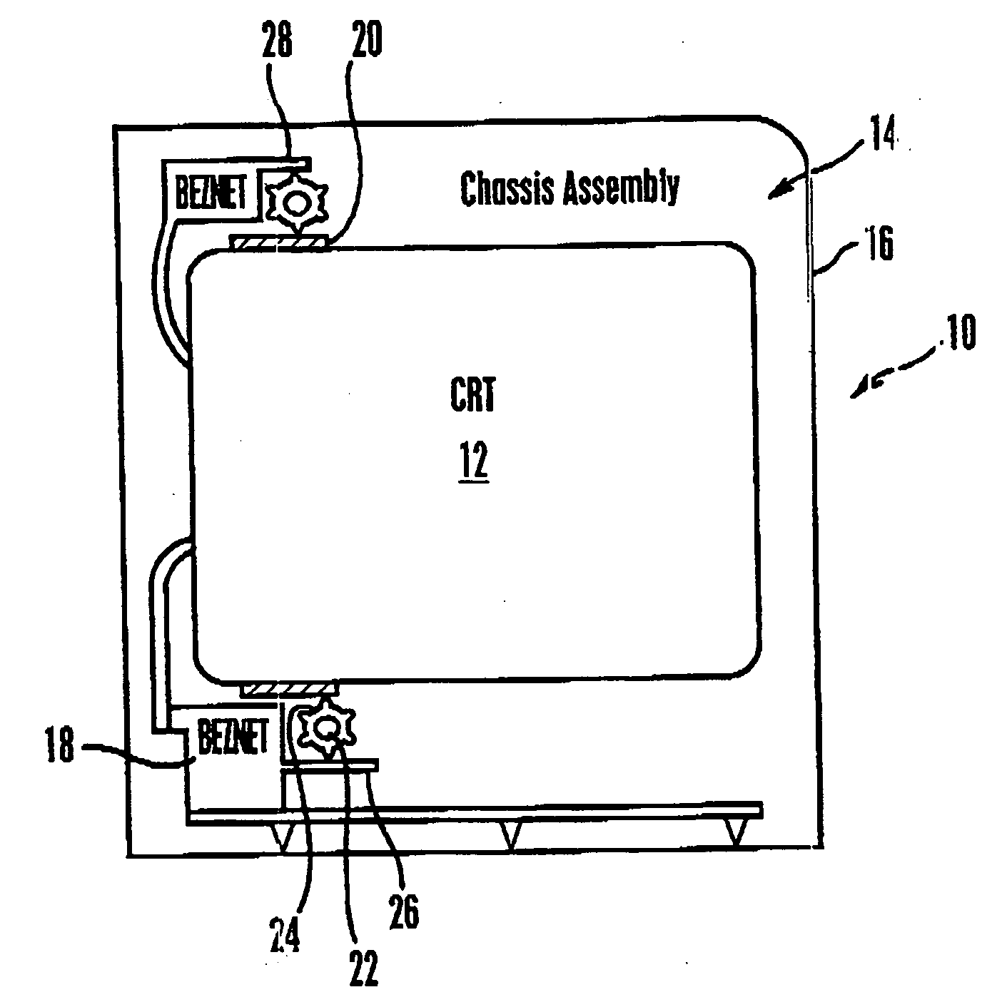
[0014] Referring initially to FIG. 1, a cathode ray tube (CRT) system embodied for illustration as a television system is shown, generally designated 10, that includes a CRT 12 or equivalent display and a chassis assembly 14. The chassis assembly 14 may include an outer housing 16 and structure interior to the housing 16, such as a halogen free, flame retardant support structure 18 colloquially known as “beznet”. Additionally, the system 10 may include one or more heat shrink (HS) steel anti-explosion bands 20 (only a single HS band 20 shown) that are wrapped around at least a portion of the CRT 12.

[0015] As shown in FIG. 1, one or more degaussing coils 22 are juxtaposed with the CRT 12. In the embodiment shown, two degaussing coils 22 are provided, although more could be provided if desired. The degaussing coils function in accordance with degaussing principles known in the art to degauss the system 10.

[0016]FIG. 1 shows that each coil 22 is closely received (e.g., in a tight fit...


PUM


Abstract

A resilient cylindrical degaussing coil holder with longitudinal ribs closely surrounds a degaussing coil for a cathode ray tube (CRT) to dampen mechanical noise transmission from the coil to the chassis assembly that holds the CRT.

Description

RELATED APPLICATIONS [0001] This application claims priority from U.S. provisional application Ser. No. 60 / 488,519, filed Jul. 17, 2003.I. FIELD OF THE INVENTION [0002] The present invention relates generally to degaussing coils for cathode ray tubes. II. BACKGROUND OF THE INVENTION [0003] Cathode ray tubes (CRTs) in general rely upon either electromagnetic or electrostatic deflection to scan an electron beam across a phosphor screen. Upon impact by electrons, the phosphors within the screen emit visible light in one or more colors. Large screen CRTs used in direct view television sets rely upon electromagnetic deflection generated by a yoke that is affixed to the neck of the CRT near the junction of the neck and the funnel of the CRT envelope. [0004] Because certain components within the CRT, such as an inner magnetic shield, an aperture grill and a frame for the aperture grille, may become magnetized because of (1) magnetic fields generated by the yoke, or (2) other components wit...

Claims


Application Information

Patent Timeline
IPC IPC(8): H01J29/00H01J29/86
CPCH01J29/867H01J29/003
Inventor KIM, BRIAN JOOSUNGZAMALOFF, JARED LEE
Owner SONY CORP
Why Eureka
Try Eureka