Illumination device

a technology of illumination device and lumbar surface, which is applied in vehicle spotlighting, lighting and heating apparatus, transportation and packaging, etc., can solve the problems of difficult to precisely illuminate a necessary area, inability to accurately grasp the position of a seat, and other occupants in the surrounding environment to feel unpleasant, so as to achieve the effect of effectively lighting any one of the areas

Inactive Publication Date: 2005-01-20
TOYODA GOSEI CO LTD
View PDF6 Cites 20 Cited by
  • Summary
  • Abstract
  • Description
  • Claims
  • Application Information

AI Technical Summary

Benefits of technology

[0017] A further object of the invention is to provide an illumination device which is small-sized to make setting place of the illumination device easy and which is excellent in design.
[0089] As described above, LED light sources are used in the invention. Because the LED light source is small in size, the size and thickness of the illumination device can be reduced as a whole. Hence, the mount space can be reduced, so that the illumination device does not occupy the space in the interior of the vehicle wastefully. Moreover, because the LED light source is small in size, the degree of freedom for the mount position is enhanced and interior design is excellent.

Problems solved by technology

In such an illumination form, it is impossible to grasp the position of a seat accurately or improve visibility at the occupant's step or the like sufficiently though an occupant can roughly grasp the interior of the vehicle when the occupant gets into the vehicle or out of the vehicle in the night or the like.
It is difficult to illuminate a necessary area precisely when an occupant in the passenger seat or in the rear seat needs a light while the vehicle is running.
That is, there is fear that the surroundings of the necessary area may be illuminated to make the other occupants in the surroundings feel unpleasant.
Moreover, because the amount of heat generated in the bulb is large, the bulb is unsuitable for continuous use in an ON state for a long time.
Hence, the related-art illumination device cannot be used for the purpose requiring long-time illumination, for example, as a reading light in the rear seat.
The purpose of use of the related-art illumination device is therefore restricted within a narrow range.
Hence, the form of illumination by the related-art illumination device is monotonous.
In addition, when the bulb is used, it is undesirable that ambient parts (such as a cover) are disposed in proximity to the bulb because of the large amount of heat generated in the bulb switched on.
This is a cause of hindrance to reduction in size.
There is fear that the boosting circuit may generate electric noise or magnetic field to exert influence on ambient parts.
When, for example, a chip type LED is used, it is however impossible to form an illumination device capable of radiating parallel light beams by simply using the LED directly because diffused light is radiated from the LED.
On the other hand, when a round type (lamp type) LED is used, it is possible to narrow range light to a certain degree in accordance with the shape of a sealing resin (molding member) but it is not easy to obtain parallel light beams.
For this reason, the requirements for reduction in size and thickness of the illumination device cannot be satisfied.
The purpose of use of the illumination device using an LED is therefore limited.

Method used


Image

  • Illumination device
  • Illumination device
  • Illumination device

Examples


first embodiment

[0126] The specific configuration of the invention will be described below with reference to the drawings.

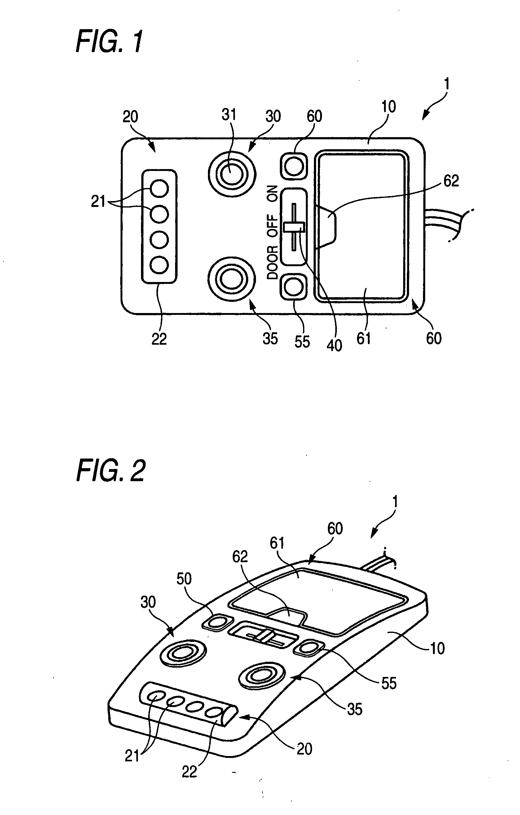
[0127]FIG. 1 is a plan view showing the design surface side of a vehicle interior illumination device 1 (hereinafter referred to as “illumination device 1”) which is an embodiment of the invention. FIG. 2 is a perspective view of the illumination device 1.

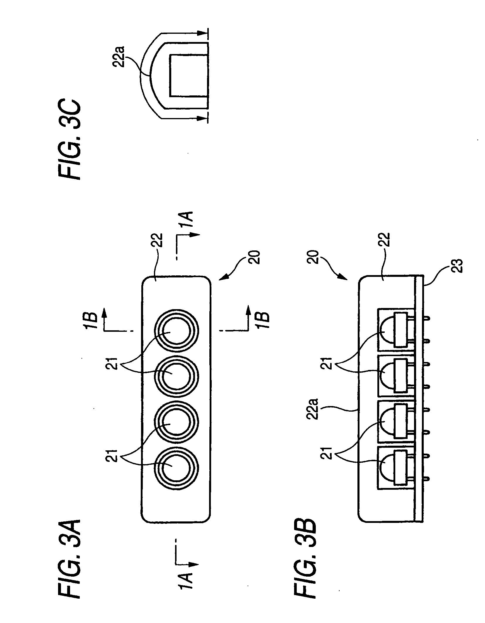
[0128] The illumination device 1 is roughly shaped like a thin plate. The illumination device 1 has a casing 10, a main illumination section (first light-emitting section) 20, two spot illumination sections (second light-emitting sections) 30 and 35, a main switch 40, two spot illumination switches 50 and 55, and a storage section 60.

[0129] The casing 10 is made of a light-proof resin (a resin colored in gray in this embodiment). The main illumination section 20, the spot illumination sections 30 and 35, etc. are disposed on the design surface side of the casing 10.

[0130] The main illumination section 20 is provided in an e...

second embodiment

[0148] The specific configuration of a second embodiment of the invention will be described below with reference to the drawings.

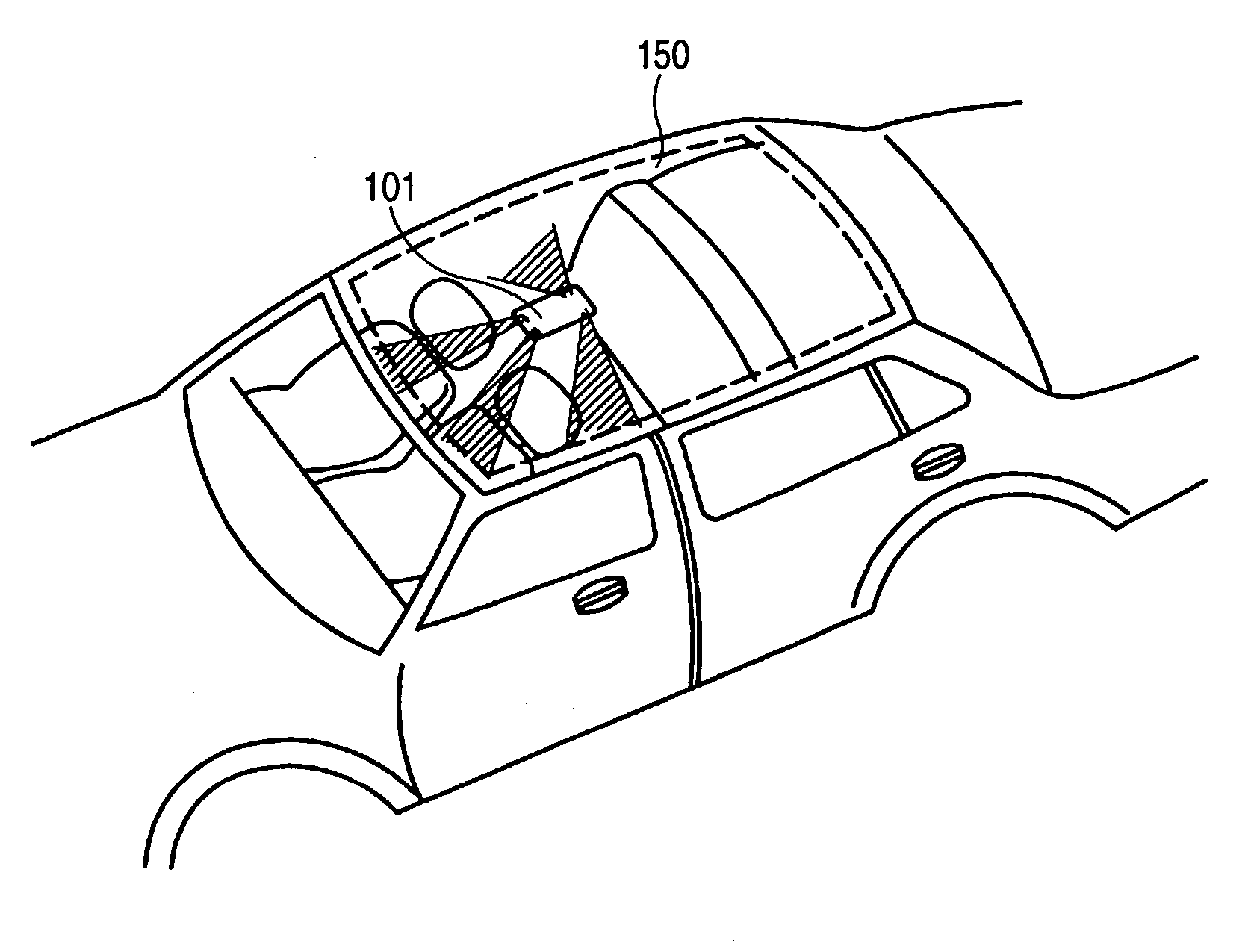
[0149]FIG. 7 is a plan view showing the design surface side of a vehicle interior illumination device 101 (hereinafter referred to as “illumination device 101”) which is an embodiment of the invention. FIG. 8 is a perspective view of the illumination device 101.

[0150] The illumination device 101 is roughly shaped like a thin plate. The illumination device 101 has a casing 110, a plurality of LEDs 121 to 125, a cover 130, and a switch 140. The casing 110 has a rectangular opening portion for light emission, and an opening portion for the switch 140. The opening portions are provided in one surface of the casing 110. Each of the LEDs 121 to 125 is a round type LED which emits umber light. LEDs 125 disposed in the central portion of the illumination device 101 are fixed onto a board not shown so that the optical axis of each of the LEDs 125 is substantially...

third embodiment

[0168]FIG. 16 is a plan view of a vehicle interior illumination device 201 (hereinafter referred to as “illumination device 201”) which is a third embodiment of the invention. FIG. 17 is a side view of the illumination device 201. FIG. 18 is a partly back view of the illumination device 201. FIG. 19 is a sectional view taken along the line 3C-3C in FIG. 16. FIG. 20 is a plan view of the illumination device 201 from the arrow 3A in FIG. 17. FIG. 21 is a partly enlarged view of the illumination device 201 depicted in FIG. 19.

[0169] The illumination device 201 has an illumination section 202, an arm section 203, and an attachment section 204.

[0170] The illumination section 202 has a board 210, chip type LEDs 220, a first lens plate 230, and a second lens plate 240. These members are received in a casing 250. Each of the chip type LEDs 220 is an LED for emitting white light.

[0171] The chip type LEDs 220 are mounted on the board 210 so that the chip type LEDs 220 are arranged as a mat...


PUM


Abstract

The invention is directed to provide a vehicle interior illumination device which has a high illuminating effect and which can be used for various kinds of illumination in a vehicle. The illumination device disposed in a roof portion of the interior of a vehicle, including: a first light-emitting section having a first light source constituted by a plurality of first LEDs disposed at substantially regular spaces; and a second light-emitting section having a second light source constituted by a second LED, and a second outer lens with which a light emission side of the second light source is covered and by which light emitted from said second light source is converged and radiated out.

Description

[0001] The present application is based on Japanese Patent Applications Nos. 2001-377181, 2001-363286, 2002-005740 and 2002-143756, the entire contents of which are incorporated herein by reference. BACKGROUND OF THE INVENTION [0002] 1. Field of the Invention [0003] The present invention relates to an illumination device for the interior of a vehicle. Particularly, it relates to an illumination device disposed in a roof portion of the interior of a vehicle so as to be used for illuminating the interior of the vehicle or an illumination device provided in the interior of a vehicle, the interior of an airplane or the like, for example, to be used as a reading light for illuminating a place close to occupant's hands. [0004] 2. Related Art [0005] For example, in a roof portion of the interior of a vehicle such as a car, an illumination device (room lamp) for illuminating the interior of the vehicle is disposed for the purpose of improving safety when an occupant gets into the vehicle or...

Claims


Application Information

Patent Timeline
Patent Type & Authority Applications(United States)
IPC IPC(8): B60Q3/00B60Q3/02
CPCB60Q3/001B60Q3/0263Y10S362/80B60Q3/0286B60Q3/0279B60Q3/74B60Q3/85B60Q3/56B60Q3/76B60Q2500/30
Inventor SUGIHARA, HIROSHIITO, HIROSHIKAMIYA, TAKAYUKISANO, YOSHIONAWASHIRO, MITSUHIRONODA, KAZUSHI
Owner TOYODA GOSEI CO LTD
Why Eureka
Try Eureka