
Hologram erasing method and hologram erasing apparatus

a technology of erasing method and erasing apparatus, which is applied in the direction of recording/reproducing/erasing using optical interference patterns, data recording, instruments, etc., can solve the problems of difficult to further increase the laser power of the light source for the reference light beam, long time required to overwrite new information after all of the information, and difficult to control position

Inactive Publication Date: 2005-01-20
FUJIFILM BUSINESS INNOVATION CORP
View PDF4 Cites 34 Cited by
  • Summary
  • Abstract
  • Description
  • Claims
  • Application Information

AI Technical Summary

Benefits of technology

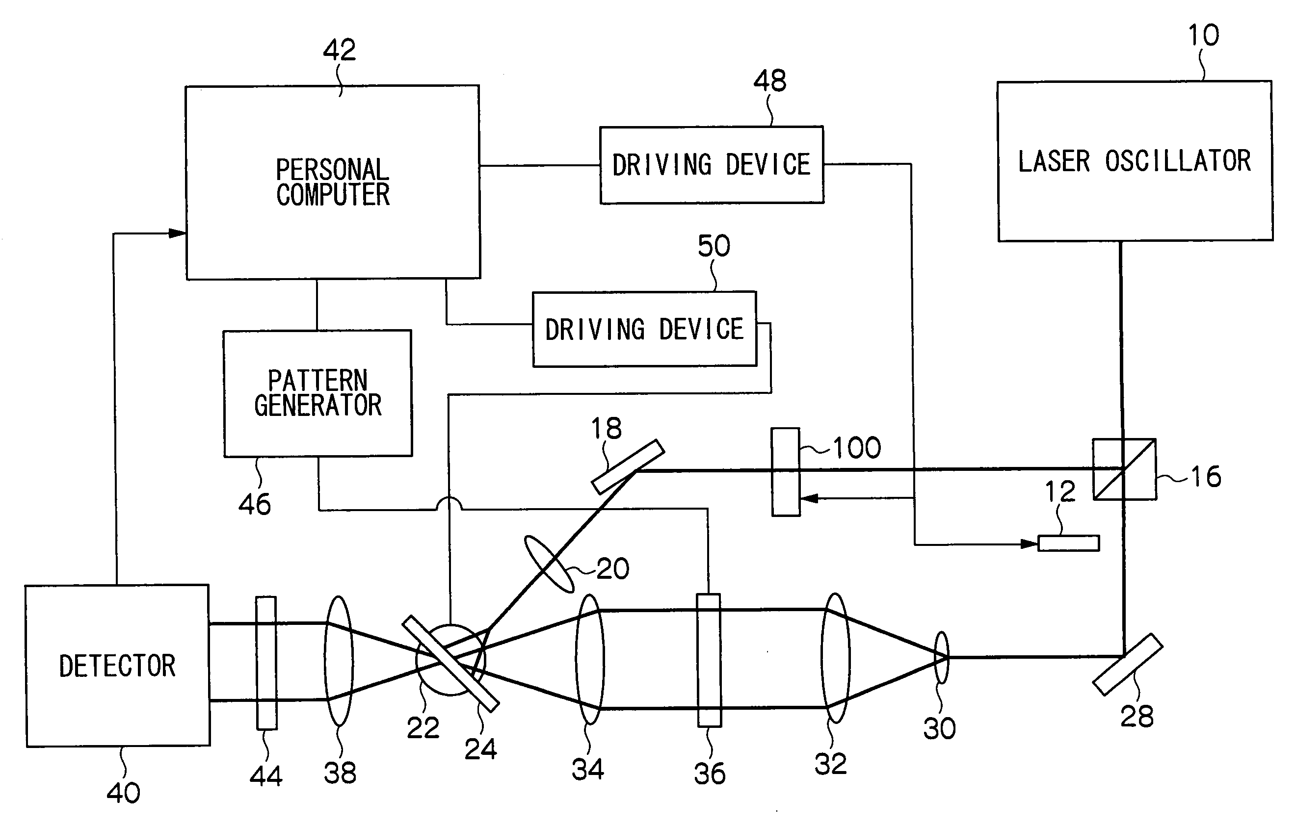
The present invention provides a simple method for selectively and completely erasing a hologram recorded in an optical recording medium. The method involves irradiating the recording region of the predetermined hologram with a reference light beam and a signal light beam that holds random pattern data at the same time. This results in the destruction of the hologram in a simple manner. The method can be performed using a hologram erasing apparatus that includes a reference light beam and a signal light beam. The apparatus can indicate whether the recording region is a hologram erasing region and can also hold data indicating the number of times the hologram has been erased. The method and apparatus can be used in various types of hologram recording, such as angle multiplex recording and shift multiplex recording.

Problems solved by technology

However, in the method in which the recorded information is erased at once, for the recording mediums having large capacities of more than 100 GB, there is a problem in that a long time is required to overwrite new information after all of the information is erased.
However, in the method in which the hologram is erased by irradiating the hologram with the reference light beam, there is the problem shown below.
Accordingly, it is difficult to further increase the laser power of the light source for the reference light beam during the erasing process.
In the method in which the information is selectively erased by the signal light beam and the reference light beam used for the recording of the magneto-optical recording medium, it is necessary that the same position as the recording be irradiated with the signal light beam, and there is the problem that position control becomes difficult as an mount of information increases.

Method used


Image

  • Hologram erasing method and hologram erasing apparatus
  • Hologram erasing method and hologram erasing apparatus
  • Hologram erasing method and hologram erasing apparatus

Examples


Embodiment Construction

[0041] One embodiment, in which the hologram erasing method of the present invention is applied to data erasing in digital hologram storage, will be described in detail below referring to the accompanying drawings.

[0042] (Fourier Transform Hologram)

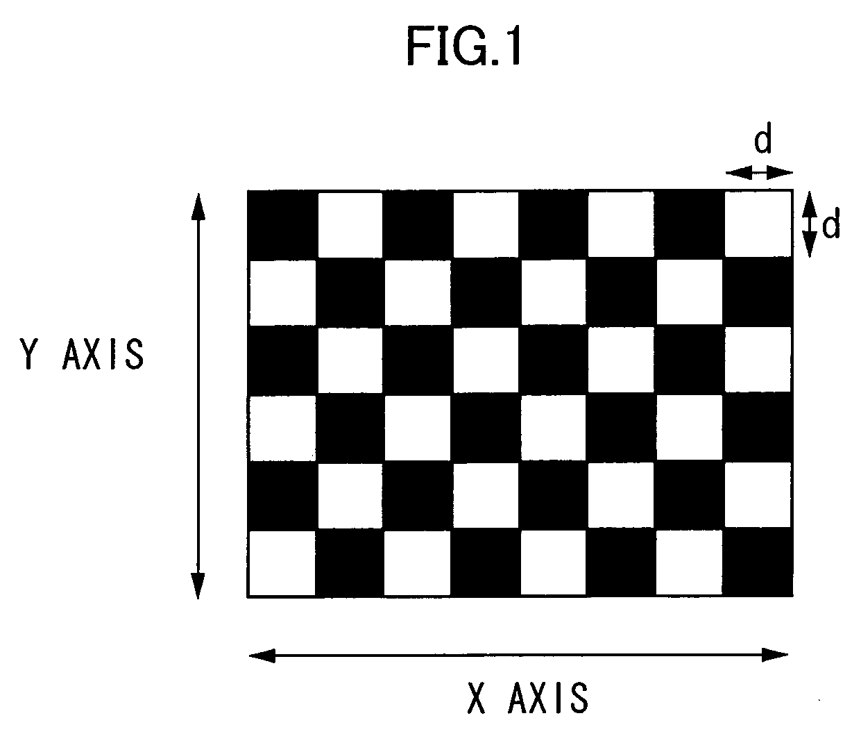
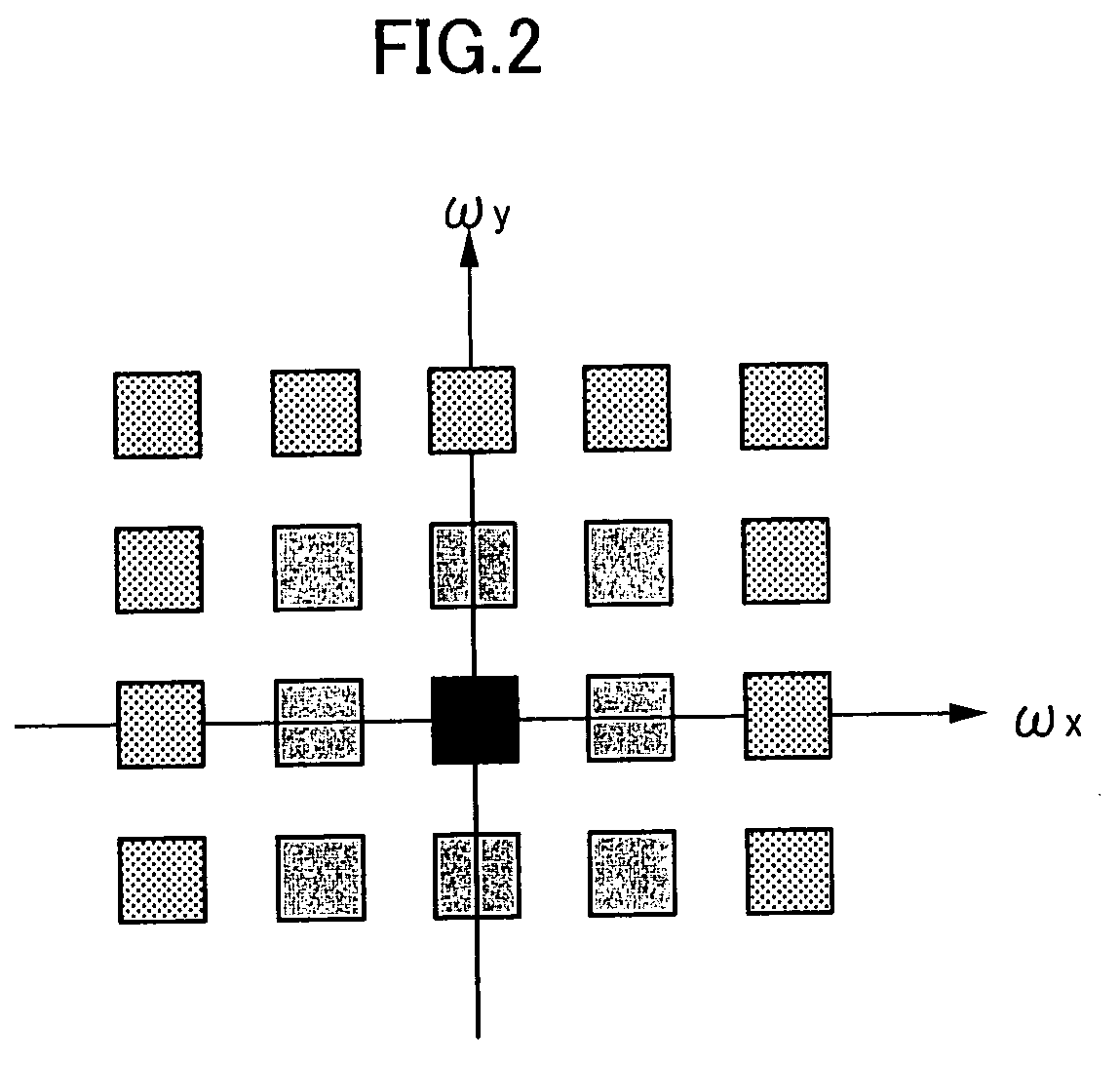
[0043] For example, an image as shown in FIG. 1 is adopted as a data page to be recorded as the hologram. A white part in FIG. 1 indicates data “1” and a black part in FIG. 1 indicates data “0”. This allows binary digital data to be recorded in each page. In this case, a size of one pixel of d by d corresponds to one bit data. In the case where such data image as described above is recorded in the form of the hologram, a Fraunhofer diffraction image of the data image is recorded by the lens in order to improve the recording density. As the Fraunhofer diffraction image of the data image is proportional to the Fourier transformation of an amplitude distribution of the data image, the Fraunhofer diffraction image is referred to as a Fourie...


PUM

PropertyMeasurementUnit
focal distanceaaaaaaaaaa

Abstract

The present invention discloses a hologram erasing method, in which a predetermined hologram is erased by irradiating a predetermined region of a hologram recording medium in which the hologram to be erased is recorded with a reference light beam and a signal light beam holding a random data pattern at the same time. In this method, the signal light beam and the reference light beam interfere with each other in the medium, and a Fourier transform hologram recorded in the region where the interference occurs is destroyed and erased by interference light beam. That is, a data page for erasing including a random pattern is overwritten to erase an original data page. According to the present invention, the hologram recorded in the optical recording medium can be selectively and completely erased in a simple method.

Description

CROSS-REFERENCE TO RELATED APPLICATION [0001] This application claims priority under 35 USC 119 from Japanese Patent Application No. 2003-197376, the disclosures of which are incorporated by reference herein. BACKGROUND OF THE INVENTION [0002] 1. Field of the Invention [0003] The present invention relates to a hologram erasing method and a hologram erasing apparatus, particularly to the hologram erasing method and the hologram erasing apparatus for selectively erasing a hologram, which has been already recorded, from an optical recording medium. [0004] 2. Description of the Related Art [0005] Holographic memory has been receiving attention as a computer file memory of the next generation. The holographic memory has both large capacity derived from a three-dimensional recording region and high speed derived from a two-dimensional batch recording and reproducing method. [0006] In the holographic memory, a plurality of data pages can be recorded by multiplexing the data pages in the sa...

Claims


Application Information

Patent Timeline
Patent Type & Authority Applications(United States)
IPC IPC(8): G03H1/02G03H1/26G11B7/00G11B7/0055G11B7/0065G11B7/135
CPCG11B7/0065G11B7/0055
Inventor KAWANO, KATSUNORIMINABE, JIROYASUDA, SHINMARUYAMA, TATSUYAMATSUI, NORIE
Owner FUJIFILM BUSINESS INNOVATION CORP
Learn More