Methods and apparatus for providing test access to asynchronous circuits and systems

a technology of asynchronous circuits and access devices, applied in the direction of transmission monitoring, line-transmission details, instruments, etc., can solve the problems of difficult reading of results using conventional synchronous test equipment, synchronous design styles facing serious performance limitations, and certain asynchronous design methodologies also have difficulties with some of the same types of limitations, so as to facilitate testing.

Inactive Publication Date: 2005-01-20
INTEL CORP
View PDF29 Cites 8 Cited by
  • Summary
  • Abstract
  • Description
  • Claims
  • Application Information

AI Technical Summary

Benefits of technology

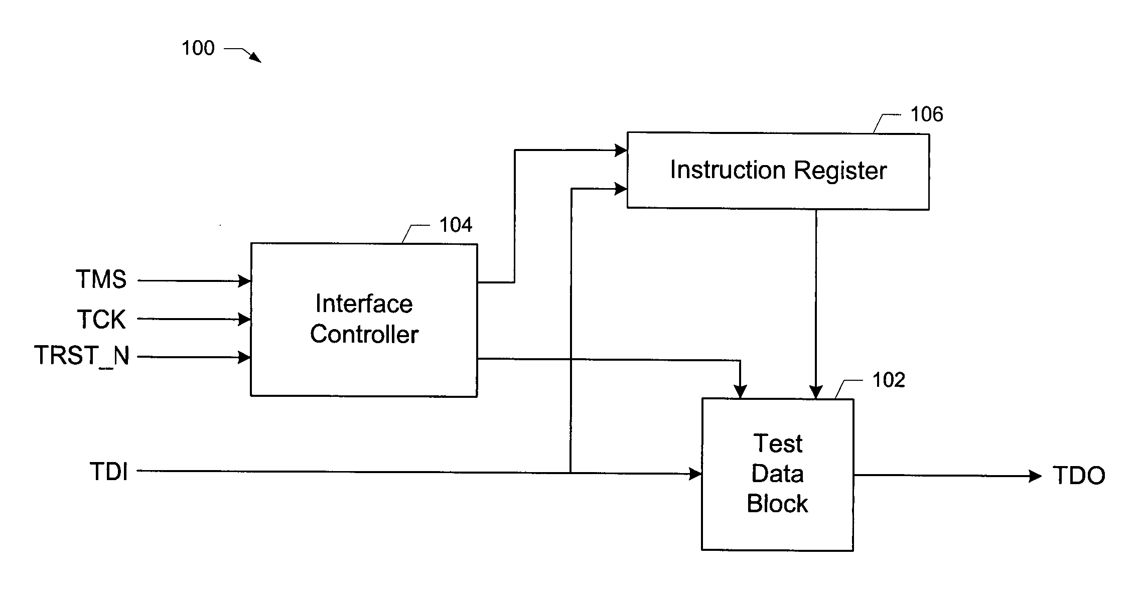
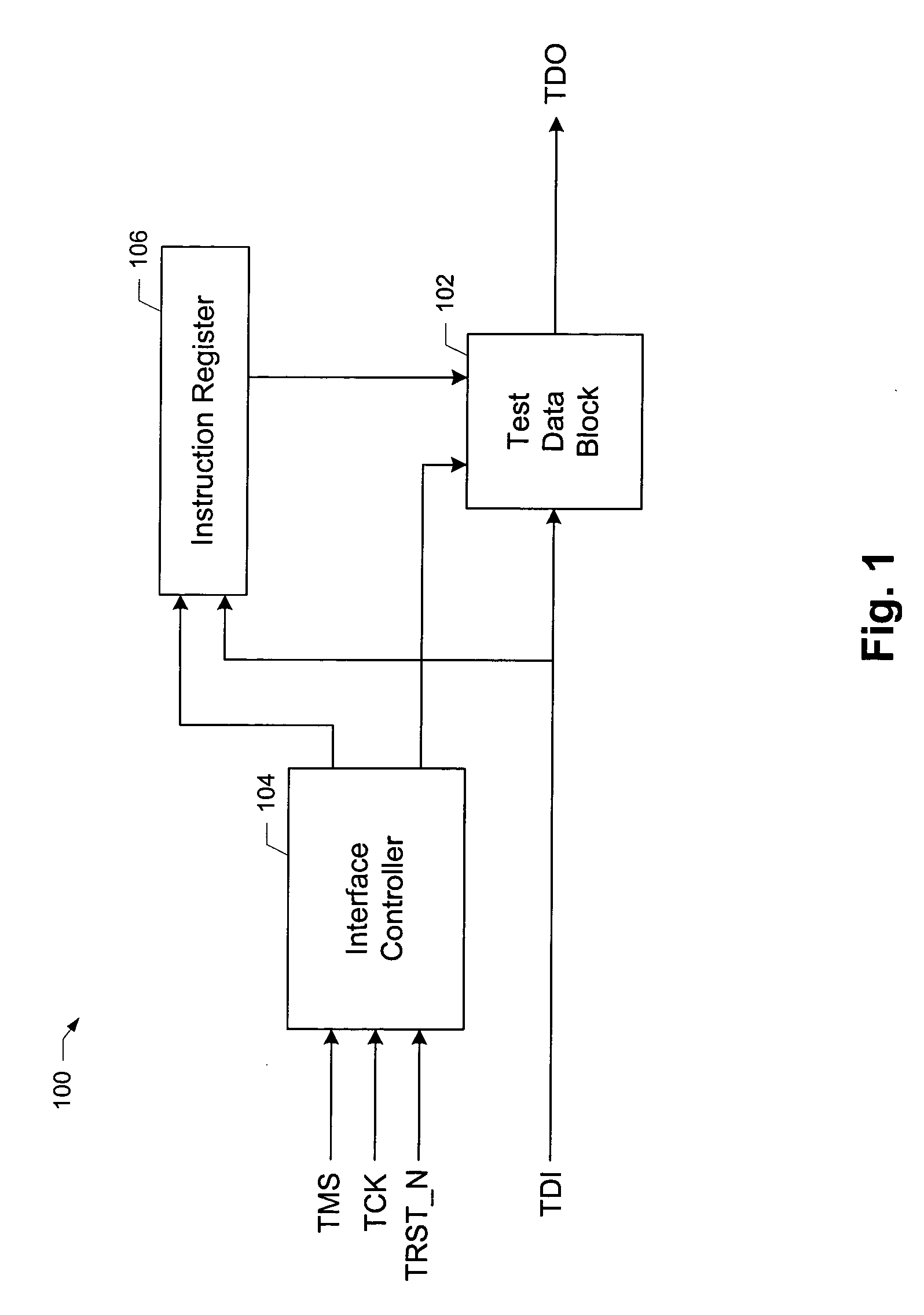
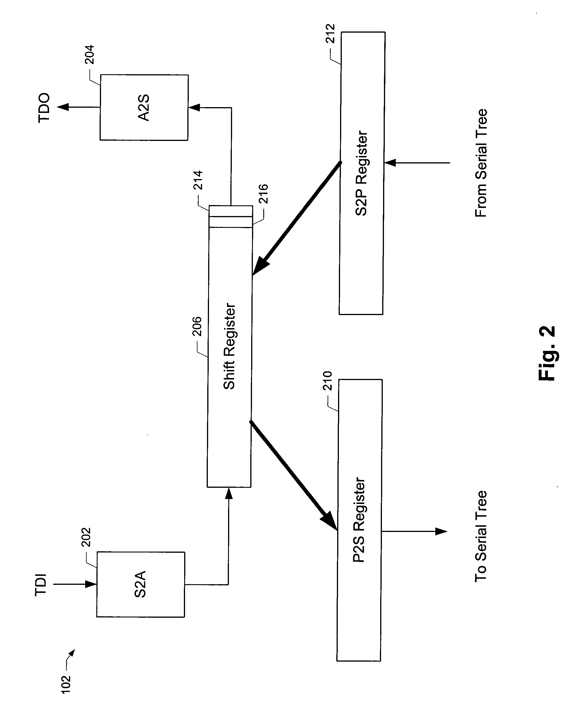
[0008] According to the present invention, methods and apparatus are provided for facilitating conversion back and forth between a serial bit stream in a synchronous domain and a message-based protocol in an asynchron

Problems solved by technology

Because of the combination of high clock rates (i.e., greater than 100 MHz) and design complexity (e.g., very large scale integration (VLSI) devices with 10 million or more transistors), signal propagation delay has become a dominant design consideration.
Delay-insensitive asynchronous designs, by their very nature are insensitive to the signal propagation delays which have become the single greatest obstacle to the advancement of traditional design paradigms.
Generally speaking, synchronous design styles are facing serious performance limitations.
Certain asynchronous design methodologies also have dif

Method used


Image

  • Methods and apparatus for providing test access to asynchronous circuits and systems
  • Methods and apparatus for providing test access to asynchronous circuits and systems
  • Methods and apparatus for providing test access to asynchronous circuits and systems

Examples


Embodiment Construction

[0016] Reference will now be made in detail to specific embodiments of the invention including the best modes contemplated by the inventors for carrying out the invention. Examples of these specific embodiments are illustrated in the accompanying drawings. While the invention is described in conjunction with these specific embodiments, it will be understood that it is not intended to limit the invention to the described embodiments. On the contrary, it is intended to cover alternatives, modifications, and equivalents as may be included within the spirit and scope of the invention as defined by the appended claims. In the following description, numerous specific details are set forth in order to provide a thorough understanding of the present invention. The present invention may be practiced without some or all of these specific details. In addition, well known process operations have not been described in detail in order not to unnecessarily obscure the present invention.

[0017] It ...


PUM


Abstract

Methods and apparatus are described for providing test access by synchronous test equipment to an asynchronous circuit. Synchronous-to-asynchronous (S2A) conversion circuitry is operable to receive synchronous input data serially from the synchronous test equipment and convert the synchronous input data to asynchronous input data. Asynchronous logic is operable to transmit the asynchronous input data to a first test register in the asynchronous circuit, and to transmit asynchronous output data received from a second test register in the asynchronous circuit. The asynchronous output data results from application of the asynchronous input data to the asynchronous circuit. Operation of the asynchronous logic is synchronized at least in part with a clock signal associated with the synchronous test equipment. Asynchronous-to-synchronous (A2S) conversion circuitry is operable to receive the asynchronous output data from the asynchronous logic, convert the asynchronous output data to synchronous output data, and serially transmit the synchronous output data to the synchronous test equipment.

Description

RELATED APPLICATION DATA [0001] The present application claims priority from U.S. Provisional Patent Application entitled METHODS AND APPARATUS FOR PROVIDING TEST ACCESS TO ASYNCHRONOUS CIRCUITS AND SYSTEM filed on Jul. 14, 2003 (Attorney Docket No. FULCP010P), the entire disclosure of which is incorporated herein by reference for all purposes. BACKGROUND OF THE INVENTION [0002] The present invention relates to asynchronous digital circuit design and in particular to the testing of asynchronous circuits and systems. [0003] The ever increasing demand for simultaneously faster and more complex digital circuits, e.g., microprocessors, has pushed conventional digital circuit design methodologies to their limits. Because of the combination of high clock rates (i.e., greater than 100 MHz) and design complexity (e.g., very large scale integration (VLSI) devices with 10 million or more transistors), signal propagation delay has become a dominant design consideration. It has become clear tha...

Claims


Application Information

Patent Timeline
IPC IPC(8): G01R31/3185H04B3/46
CPCG01R31/31726G11C2029/5602G01R31/318594
Inventor MOACANIN, MICHEL A.BOULTON, JEREMYNOVAK, STEVEN
Owner INTEL CORP
Why Eureka
Try Eureka