UWB (Ultra Wide Band) interference mitigation

a wide band, interference-reducing technology, applied in the field of communication systems, can solve the problems of not being implemented, large synchronization, and difficult to achieve, and achieve the effect of reducing the number of synchronizations

Active Publication Date: 2005-01-20
AVAGO TECH INT SALES PTE LTD
View PDF6 Cites 45 Cited by
  • Summary
  • Abstract
  • Description
  • Claims
  • Application Information

AI Technical Summary

Benefits of technology

FIG. 19 is a diagram illustrating another embodiment of a piconet operable device that supports functionality of interference compensation capitalizing on structured interference (showing PHY (physical layer), MAC (Medium Access Controller), and higher protocol layers) according to the invention.

Problems solved by technology

However, other piconets may be implemented such that the devices do not operate according to such an M / S (Master / Slave) type relationship.
However, within a scatternet implementation, a problem may arise such that each of the individual piconets must be able to operate in relative close proximity with other piconets without interfering with one another.
This inherently requires a great deal of synchronization between the piconets, which may be very difficult to achieve in some instances.
It is also noted that independently operating piconets, not implemented within a scatternet implementation, may also suffer from deleterious effects of interference with other piconets located within relative close proximity.
As briefly referred to above, as the proximity of piconets continue to grow ever closer, there is a problem that arises when the communication between the various piconets interfere with one another.
For example, when communication between a user device and a piconet controller in one piconet is ongoing, and communication between another user device and its corresponding piconet controller in another piconet is also ongoing simultaneously, interference between the two paths of communication can cause degradation in the throughput of both of the communication paths.
Moreover, even peer to peer communication between the two user devices in a first piconet and two other user devices in a second piconet may also generate the undesirable interference between the two piconets.
Moreover, when adjacent piconets are transmitting using different hopping patterns, the signals can collide even once per period, resulting in a spreading gain of N. In most of these TG3a proposals, the time per hop is much greater than the inverse of the bandwidth of each frequency band, meaning that there is inevitably extra “dead time” that occurs between the various pulses of the communication within the piconet.
One of the detrimental effects of such a proposal is that these proposed communication systems do not achieve the full available spreading gain.
Currently, there does not exist in the art a sufficient solution that may accommodate the undesirable effects of symbol collisions within such piconets in a satisfactory manner.
While there have been some attempts to try to deal with minimizing these undesirable symbol collisions within such piconets, there does not yet exist a satisfactory manner in which symbol collisions (when they do in fact occur) may be dealt with while maintaining a very high level of performance for all of the devices within the piconet.

Method used


Image

  • UWB (Ultra Wide Band) interference mitigation
  • UWB (Ultra Wide Band) interference mitigation
  • UWB (Ultra Wide Band) interference mitigation

Examples


Embodiment Construction

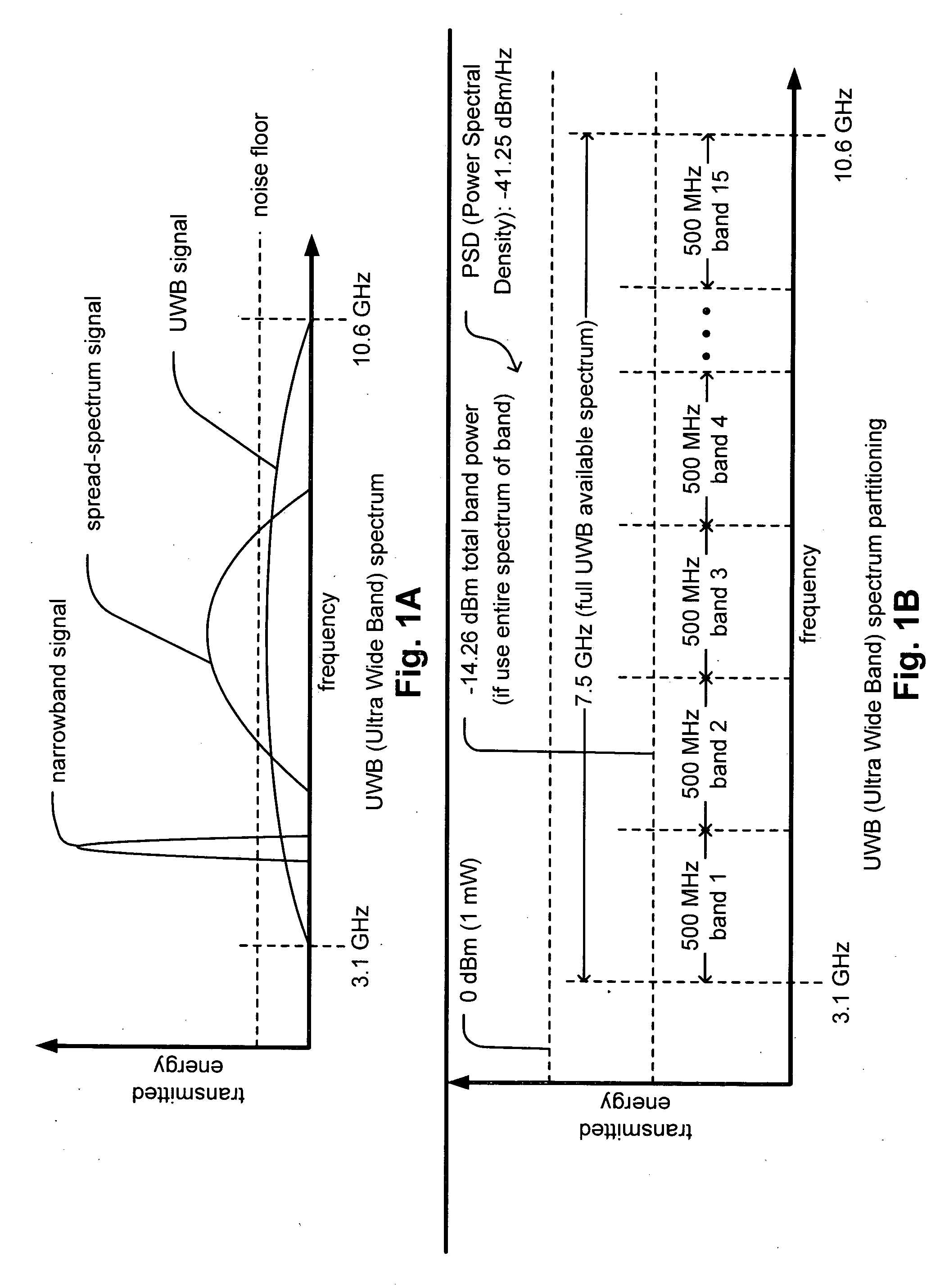
FIG. 1A is a diagram illustrating an embodiment of the frequency spectrum of a UWB (Ultra Wide Band) signal when compared to some other signal types according to the invention. In contradistinction to RF (Radio Frequency) communications that operate by using a narrowband carrier frequency to transmit information, UWB communications operate by sending pulses of energy across a broad frequency spectrum. For example, an RF signal may be viewed as occupying the range of spectra of a narrowband frequency. Also, in contradistinction to a spread-spectrum signal whose intensity (magnitude) generally rises above the noise floor within an available spectrum and also occupies a relatively narrower portion of the available spectrum, a UWB signal may actually be viewed as pulse shaped noise (that may never exceed the noise floor within the available spectrum). A spread-spectrum signal may be viewed as a signal that occupies a frequency band that is much wider than the minimum bandwidth required ...


PUM


Abstract

UWB (Ultra Wide Band) interference mitigation. A novel solution is presented whereby various piconet operable devices are operated to support a relatively structured interference pattern. The devices operate cooperatively (e.g., within multiple piconets that may be in relatively close proximity) such that undesirable symbol collisions generate relatively structured interference (e.g., a structured interference pattern). A piconet operable device (e.g., a communication transceiver or receiver) operating therein includes intelligence such that it may detect a symbol that has undergone an undesirable symbol collision. Then, after those symbols have been identified, they may be modified appropriately so the overall performance of the piconet may be kept at a high performance level. For example, those symbols having an energy (or power) above a predetermined threshold (such as an expected energy level or a power level) may be appropriately de-weighted.

Description

BACKGROUND OF THE INVENTION TECHNICAL FIELD OF THE INVENTION The invention relates generally to communication systems; and, more particularly, it relates to receive processing (demodulation and decoding) of signals received within such communication systems. DESCRIPTION OF RELATED ART Data communication systems have been under continual development for many years. In recent years, the development of piconet type communication systems has been under increasing development. A piconet may be viewed as a network that is established when two devices connect to support communication of data between themselves. Sometimes, piconets are referred to as PANs (Personal Area Networks). These piconets typically operate within a region having a radius of up to approximately 10 meters. As is known, the Bluetooth ® communication standard is the first such PAN communication standard that has been developed. In accordance with the Bluetooth® communication standard, the communication between the var...

Claims


Application Information

Patent Timeline
Patent Type & Authority Applications(United States)
IPC IPC(8): H04B1/69H04L27/06
CPCH04B1/719
Inventor OJARD, ERIC J.
Owner AVAGO TECH INT SALES PTE LTD
Why Eureka
Try Eureka