
Signal quality estimation in a wireless communication system

a wireless communication system and signal quality technology, applied in the field of communication systems, can solve problems such as undesirable affecting the ability of a signal, and achieve the effect of accurately estimating the quality of a received signal

Active Publication Date: 2005-01-20
AVAGO TECH INT SALES PTE LTD
View PDF7 Cites 57 Cited by
  • Summary
  • Abstract
  • Description
  • Claims
  • Application Information

AI Technical Summary

Benefits of technology

[0007] The present invention provides techniques for accurately estimating a signal quality of a received signal in a wireless communication system, the received signal typically being a baseband signal. The signal quality estimation can be employed, for example, in a receiver associated with the wireless communication system for advantageously adapting a data transmission rate of the wireless communication system to varying conditions in the system. Such varying conditions may include, for instance, impairments in a wireless communication channel associated with the system, impairments in a transceiver communicating over the wireless communication channel, etc. Channel impairments which may undesirably affect the ability of a signal to pass through the channel include, for example, co-channel interference, delayed signal interference, narrowband interference (e.g., from intermodulation products), thermal noise, etc. According to the invention, the signal quality estimation is based, at least in part, on a specific portion of a received data packet.

Problems solved by technology

Such varying conditions may include, for instance, impairments in a wireless communication channel associated with the system, impairments in a transceiver communicating over the wireless communication channel, etc.
Channel impairments which may undesirably affect the ability of a signal to pass through the channel include, for example, co-channel interference, delayed signal interference, narrowband interference (e.g., from intermodulation products), thermal noise, etc.

Method used


Image

  • Signal quality estimation in a wireless communication system
  • Signal quality estimation in a wireless communication system
  • Signal quality estimation in a wireless communication system

Examples


Embodiment Construction

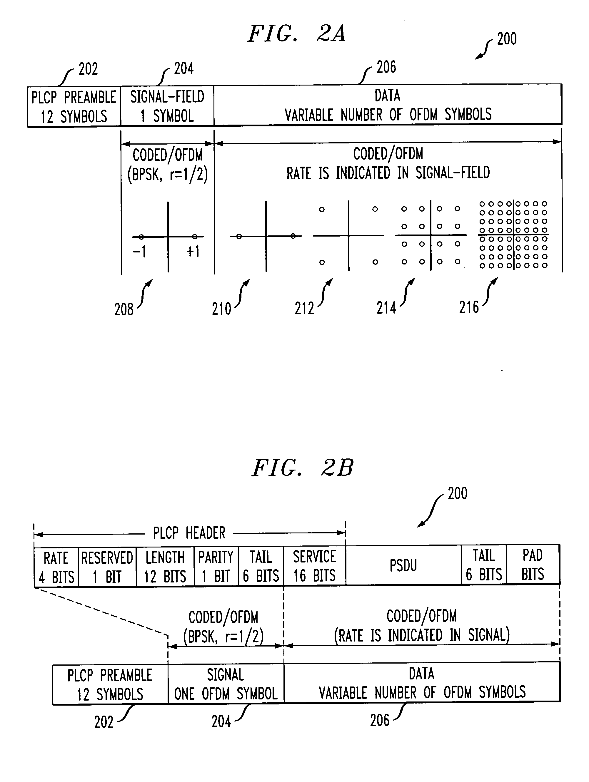
[0014] The present invention will be described herein in the context of an EEE 802.11 compliant orthogonal frequency division multiplexing (OFDM) wireless communication system. It should be appreciated, however, that the present invention is not limited to this or any particular wireless communication system. Rather, the invention is more generally applicable to techniques for accurately estimating the signal quality of a received baseband signal in a wireless communication system. The signal quality estimation may be employed, in accordance with one aspect of the invention, for optimally controlling a data transmission rate in a wireless system. Although particularly well-suited for use in conjunction with the EEE 802.11 standard, the invention can be used with other standards, as well as in non-standard systems.

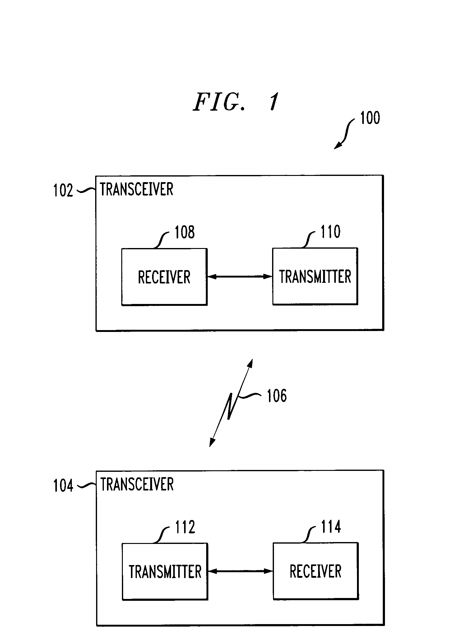
[0015]FIG. 1 depicts an exemplary wireless communication system 100 in which the methodologies of the present invention may be implemented. The exemplary wireless communic...


PUM


Abstract

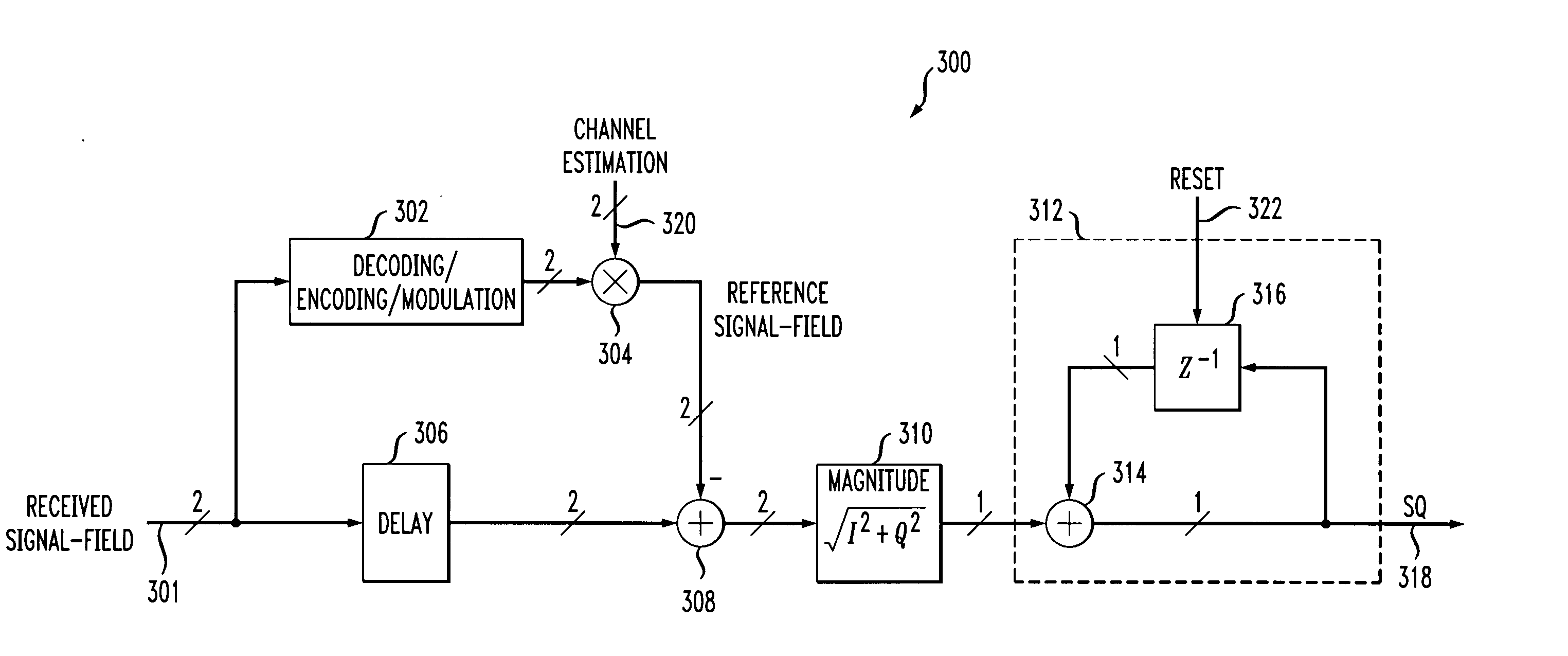
In a wireless system including a wireless communication channel, a method for estimating a signal quality of a received signal includes the steps of receiving a signal from the wireless communication channel, the received signal including at least one field that is modulated and encoded in a substantially fixed manner, and generating at least one reference field based, at least in part, on the at least one field and on a channel estimation signal. The channel estimation signal is representative of at least one characteristic of the wireless communication channel. The method further includes the step of generating a signal quality estimate as a function of the at least one field in the received signal and the generated at least one reference field.

Description

CROSS-REFERENCE TO RELATED APPLICATION(S) [0001] This application relates to commonly assigned U.S. application Ser. No. 10 / 305,554, filed on Nov. 27, 2002 and entitled “Data Transmission Rate Adaptation in a Wireless Communication System,” the disclosure of which is incorporated by reference herein.FIELD OF THE INVENTION [0002] The present invention relates generally to communication systems, and more particularly relates to techniques for estimating signal quality in a wireless communication system. BACKGROUND OF THE INVENTION [0003] In a conventional wireless communication system including a pair of transceivers communicating with one another over a wireless communication channel, there are typically a number of different data transmission rates available at which to transmit data. Generally, the higher the data rate, the more susceptible the system is to errors. Under certain circumstances, it is necessary to adapt the system to higher or lower data transmission rates based, at ...

Claims


Application Information

Patent Timeline
Patent Type & Authority Applications(United States)
IPC IPC(8): H04J11/00H04B17/00H04L1/20
CPCH04L1/208H04L1/20
Inventor BOER, JANDRIESEN, BASGIL, RA'ANANKRIEDTE, KAI ROLAND
Owner AVAGO TECH INT SALES PTE LTD
Learn More