Variable optical attenuator

Inactive Publication Date: 2005-01-20
LG ELECTRONICS INC
View PDF5 Cites 1 Cited by
  • Summary
  • Abstract
  • Description
  • Claims
  • Application Information

AI Technical Summary

Benefits of technology

[0014] An object of the present invention is to provide a variable optical attenuator that is compact in size and lightweight.
[0015] Another object of the present invention is to provide a variable optical attenuator having a more si

Problems solved by technology

When a plurality of different optical outputs is multiplexed, and when the multiplexed outputs are transmitted, then the optical output for each wavelength loses uniformity, thereby deteriorating the characteristics of the signals and ultimately disabling transmission of the signals.
However, devices such as the mechanical optical attenuator

Method used


Image

  • Variable optical attenuator
  • Variable optical attenuator
  • Variable optical attenuator

Examples


Example

[0034] Reference will now be made in detail to the preferred embodiments of the present invention, examples of which are illustrated in the accompanying drawings. Wherever possible, the same reference numbers will be used throughout the drawings to refer to the same or like parts.

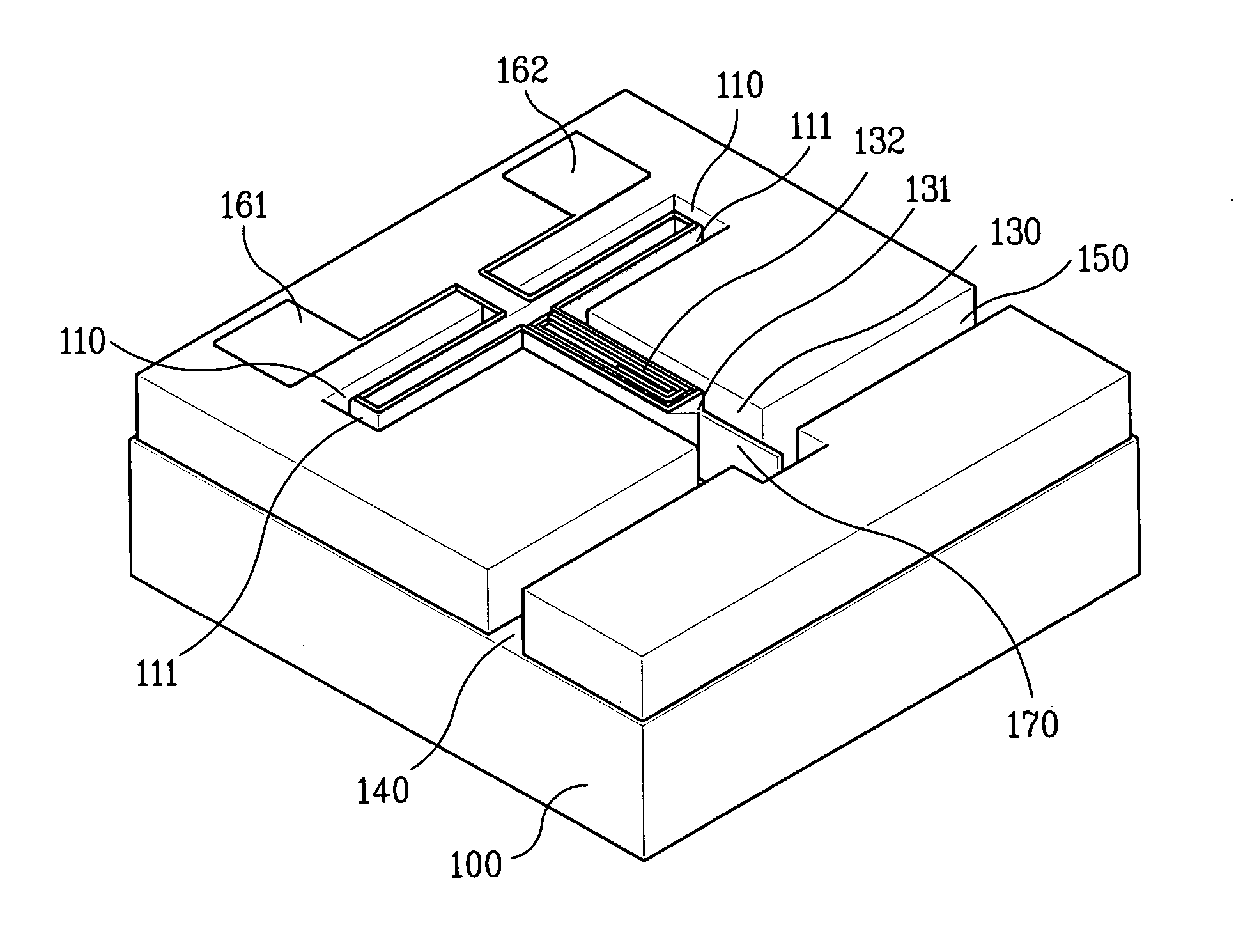
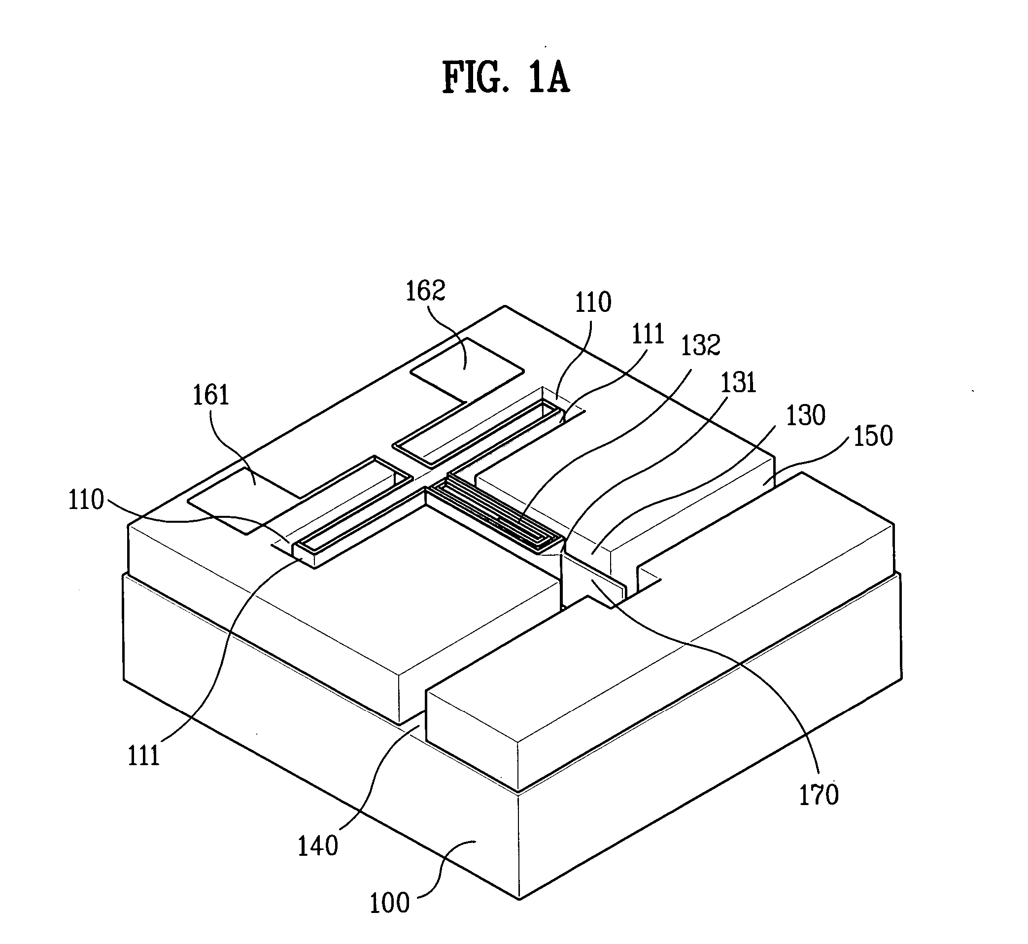
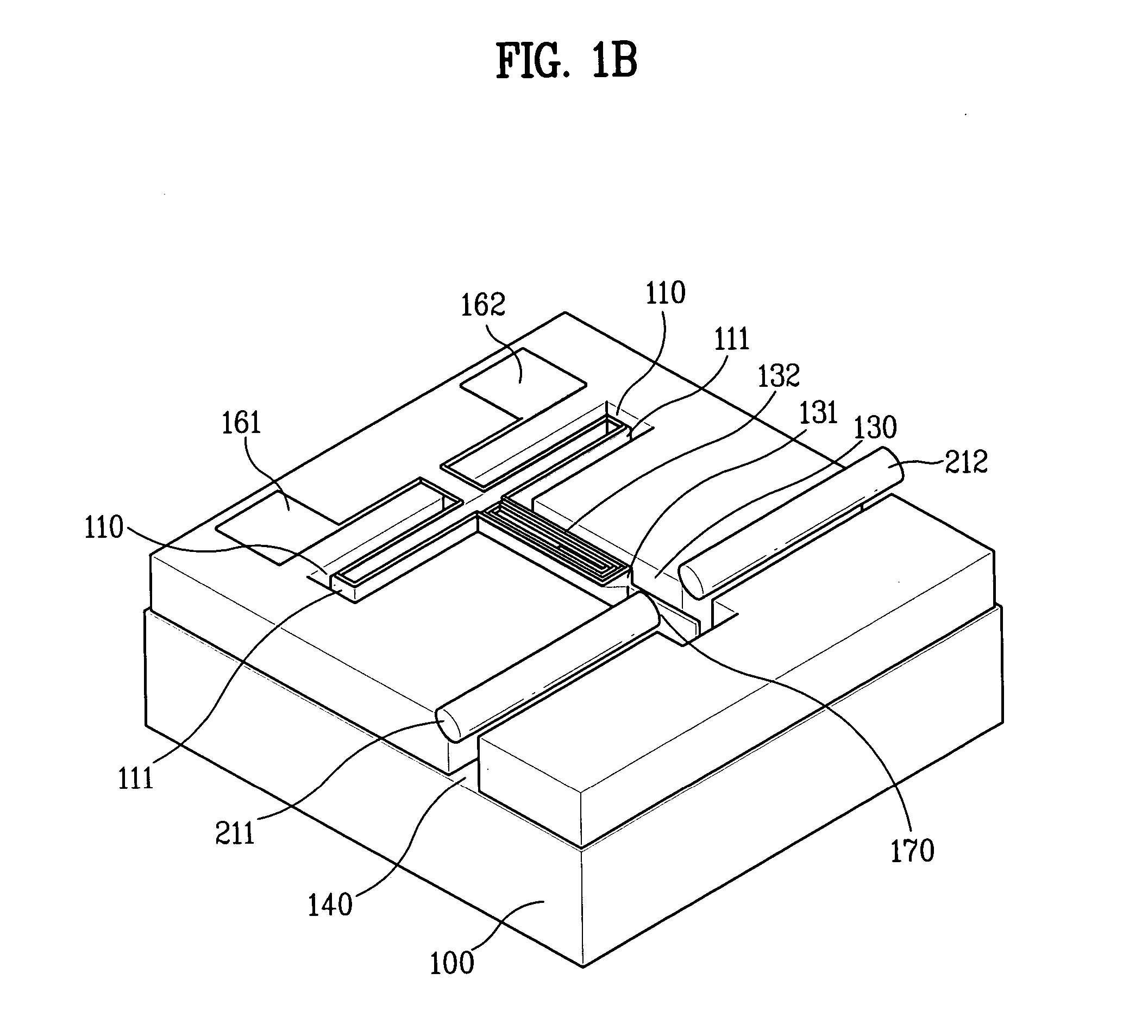
[0035]FIGS. 1A and 1B illustrate perspective views of a variable optical attenuator using an electromagnetic micromirror according to the present invention. And, FIG. 2 illustrates a plane view of the variable optical attenuator using the electromagnetic micromirror according to the present invention.

[0036] More specifically, FIG. 1A illustrates the variable optical attenuator prior to having the optical fiber mounted thereon. And, FIG. 1B illustrates the variable optical attenuator after having the optical fiber mounted thereon.

[0037] Referring to FIGS. 1A, 1B, and 2, the variable optical attenuator includes a substrate 100 having first, second, and third grooves 110, 130, and 150, an elastic body 111, ...


PUM


Abstract

A variable optical attenuator is disclosed. The attenuator includes a variable optical attenuator includes a substrate having a first groove, a second groove, and a third groove, an elastic body connected to a surface of the substrate and formed within the first groove, so as to be spaced apart from the inner surface of the first groove, a movable unit connected to the elastic body and formed within the second groove, so as to be spaced apart from the inner surface of the second groove, a micromirror connected to the movable unit and formed within the third groove, so as to be spaced apart from the inner surface of the third groove, input and output optical fibers formed on each side of the micromirror within the third groove and inputting and outputting light rays depending upon a displacement of the micromirror, and a coil formed on the movable unit having the elastic body formed thereon and moving the movable unit and the micromirror in a vertical direction depending upon external electrical signals, so as to control an intensity of light from the output optical fiber.

Description

CROSS-REFERENCE TO RELATED APPLICATIONS [0001] This application claims the benefit of Korean Application No. P10-2003-0049193, filed on Jul. 18, 2003, which is hereby incorporated by reference as if fully set forth herein. BACKGROUND OF THE INVENTION [0002] 1. Field of the Invention [0003] The present invention relates to an optical switch used in an optical communication network, and more particularly, to a variable optical attenuator having a micromirror. [0004] 2. Discussion of the Related Art [0005] A wavelength division multiplexed optical communication system are widely developed supplied in order to effectively transmit various forms of information that are currently in mass production. [0006] In such optical communication systems, a plurality of types of information are stored in a plurality of light sources having each different wavelengths, which are then mulitiplexed in order to be transmitted through a single optical fiber. Then, a receiving terminal demultiplexes the mu...

Claims


Application Information

Patent Timeline
IPC IPC(8): G02B26/02B81B3/00G02B6/26G02B6/35G02B26/08
CPCG02B6/266G02B6/3514G02B6/3552G02B26/085G02B6/3594G02B26/0833G02B6/3572G02B26/02
Inventor YEE, YOUNG JOOJI, CHANG HYEON
Owner LG ELECTRONICS INC
Why Eureka
Try Eureka