Charging apparatus having auxiliary charger rubbing against image bearing member

a charging apparatus and image bearing technology, applied in the direction of instruments, nuclear engineering, corona discharge, etc., can solve the problems of affecting the production of ozone, and affecting the ability of photosensitive members to achieve desired values. , to achieve the effect of small ozone production

Inactive Publication Date: 2005-01-20
CANON KK
View PDF10 Cites 16 Cited by
  • Summary
  • Abstract
  • Description
  • Claims
  • Application Information

AI Technical Summary

Benefits of technology

[0014] It is an object of the present invention to provide a cha

Problems solved by technology

In this method, however, corona products such as ozone and nitrogen oxides are produced during the generation of corona, and these adhere to the surface of the photosensitive member or deteriorate the surface of the photosensitive member.
Therefore, the spread of an image or a faint image has been caused or the stains of a corona wire have caused the non-uniformity of charging to thereby cause a faulty image such as the blank area or black line of an image.
However, in a method wherein only a DC voltage is applied, the resistance value of the contact charging member is fluctuated by the fluctuations of the temperature and humidity around an image forming apparatus and the photosensitive member is shaved by being repetitively used, whereby the film thickness thereof is changed and a charging voltage is fluctuated and therefore, it has been difficult to bring the potential of the photosensitive member to a desired value.
Even in such a contact charging apparatus, however, the essential charging mechanism uses a discharging phenomenon from the charging member to the photosensitive member and therefore, a slight amount of ozone is produced.
Also, discharge occurs near the surface of the photosensitive member and therefore, damage to the surface of the photosensitive member by charging becomes greater than that

Method used


Image

  • Charging apparatus having auxiliary charger rubbing against image bearing member
  • Charging apparatus having auxiliary charger rubbing against image bearing member
  • Charging apparatus having auxiliary charger rubbing against image bearing member

Examples


first embodiment

[0023] (First Embodiment)

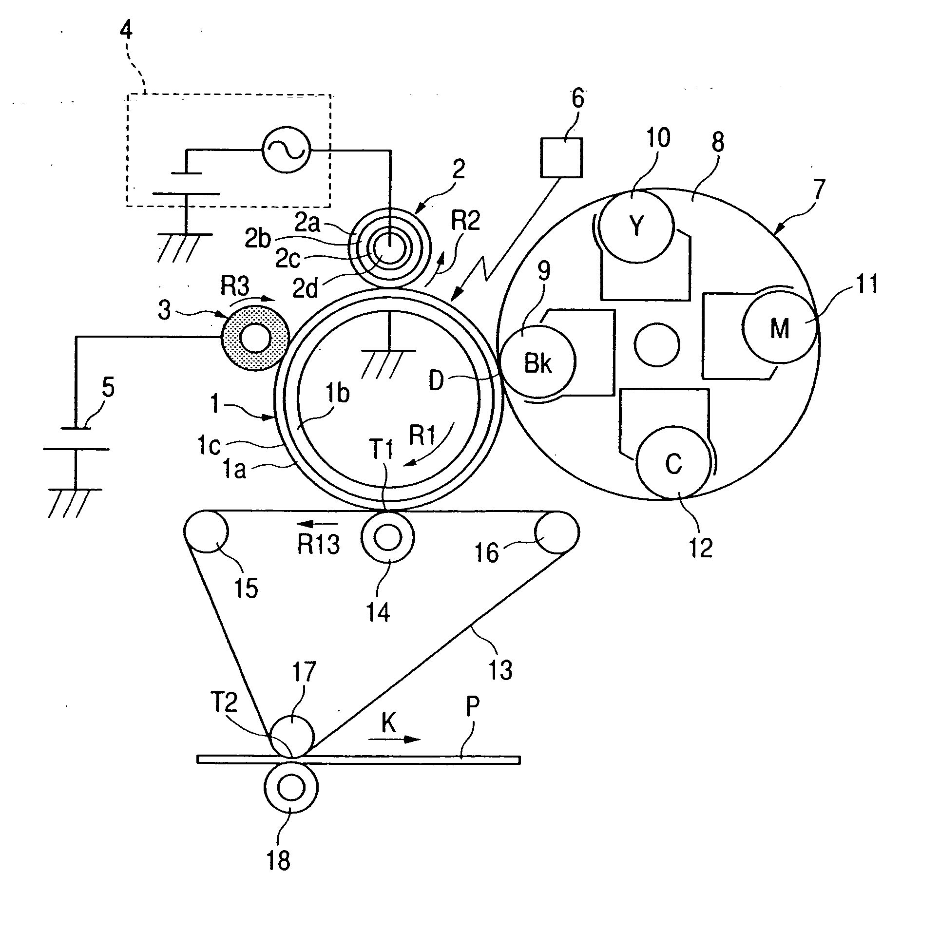
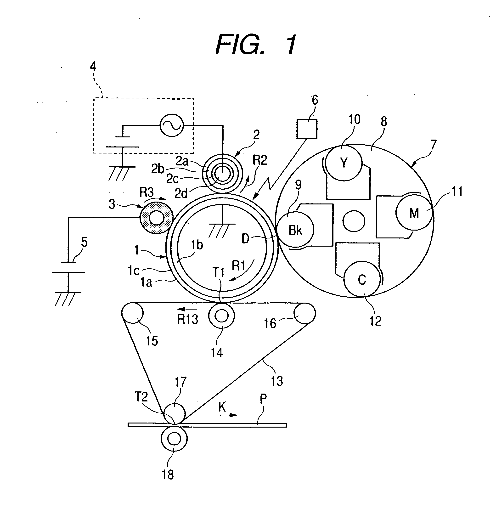
[0024]FIG. 1 shows an image forming apparatus according to a first embodiment as an example of the image forming apparatus according to the present invention. The image forming apparatus shown in FIG. 1 is a four-color full-color copying machine of an electrophotographic type using an intermediate transferring belt (intermediate transferring member, and FIG. 1 is a vertical cross-sectional view schematically showing the construction thereof. The copying machine shown in FIG. 1 is designed as a digital compound machine having, besides the copying function, a printer function and a facsimile function.

[0025] As shown in FIG. 1, the copying machine (hereinafter referred to as the image forming apparatus) is provided with a drum-shaped electrophotographic photosensitive member

[0026] (hereinafter referred to as the photosensitive drum) as an image bearing member. The photosensitive drum 1 has an electrically conductive drum base (support member) 1b of aluminum o...

second embodiment

[0047] (Second Embodiment)

[0048]FIG. 3 schematically shows the construction of an image forming apparatus according to a second embodiment. In this embodiment, members similar in function and construction to those in the above-described first embodiment are given the same reference characters and suitably need not be described.

[0049] The present embodiment is an improvement in the system shown in the first embodiment wherein a problem arises when the vomits of the transfer residuals accumulated on the surface layer of the auxiliary charging roller 3 are collected by the developing device.

[0050] The present embodiment adopts a magnetic single-component developing method (alias jumping developing) in which the developing device 9 for black effects developing by a magnetic position component developer. This is taken up as a typical example in which a problem arises when the vomits of the transfer residuals accumulated on the surface layer of the auxiliary charging roller 3 are collec...

third embodiment

[0058] (Third Embodiment)

[0059]FIG. 4 schematically shows the construction of an image forming apparatus according to a third embodiment. In this embodiment, members, etc. similar in function and construction to those in the above-described first and second embodiments are given the same reference characters and suitably need not be described.

[0060] The present embodiment is improved so that on the supposition that in the image forming apparatus according to the aforedescribed first embodiment, during so-called jam such as paper jam, the toner images developed on the photosensitive drum 1 are not transferred to the intermediate transferring belt 13, but arrive at the auxiliary charging roller 3 and the toner contamination of the auxiliary charging roller 3 occurs, the auxiliary charging roller 3 may not contaminated by the toners even during jam.

[0061] In the present embodiment, as shown in FIG. 4, a cleaning apparatus 19 is disposed upstream of the auxiliary charging roller 3 and...


PUM


Abstract

A charging apparatus has a movable image bearing member, a first charging member for charging the image bearing member, and a second charging member provided upstream of the first charging member with respect to the direction of movement of the image bearing member, the second charging member having an elastic rotary member rubbing against the image bearing member.

Description

BACKGROUND OF THE INVENTION [0001] 1. Field of the Invention [0002] The invention relates to a charging apparatus suitably used in an image forming apparatus of an electrophotographic type for charging an image bearing member such as a photosensitive member. [0003] 2. Description of Related Art [0004] In an image forming apparatus of an electrophotographic type, a corona charger has heretofore been used as charging means for a photosensitive member. In this method, however, corona products such as ozone and nitrogen oxides are produced during the generation of corona, and these adhere to the surface of the photosensitive member or deteriorate the surface of the photosensitive member. Therefore, the spread of an image or a faint image has been caused or the stains of a corona wire have caused the non-uniformity of charging to thereby cause a faulty image such as the blank area or black line of an image. [0005] In recent years, however, owing to such merits as low ozone and low electr...

Claims


Application Information

Patent Timeline
IPC IPC(8): G03G5/147G03G15/02G03G21/10
CPCY10S430/102G03G15/0233
Inventor NISHIHAMA, TADAYOSHIOGURA, TOKIHIKOHISAKUNI, HISATAKA
Owner CANON KK
Why Eureka
Try Eureka