Method of changing the duty cycle frequency of a PWM solenoid on a CAM phaser to increase compliance in a timing drive

a technology of cam phaser and duty cycle frequency, which is applied in the direction of valve drive, coupling, gearing, etc., can solve the problems of engine speed at which the resonance occurs to change, the demand for emissions control complicates matters further, and the engine speed may be undesirable, so as to reduce the resonance condition, dampen out the resonance frequency excitation, and add more compliance

Active Publication Date: 2005-01-20
BORGWARNER INC
View PDF21 Cites 8 Cited by
  • Summary
  • Abstract
  • Description
  • Claims
  • Application Information

AI Technical Summary

Benefits of technology

[0017] Accordingly, a method is used to change the duty cycle frequency of a PWM solenoid or the dither frequency of a current controlled solenoid driver to cause the spool valve to dither about null so as to increase the flow from chamber to chamber or to each portion of a cavity enclosing a 4-way control or spool valve. This increased flow will add more compliance to the timing drive system and reduce the resonance condition. The increase flow will take some energy from the timing drive and help dampen out the resonance frequency excitation.
[0018] Accordingly, in a chain drive device having a driving shaft, and a driven shaft, coupled together by an endless chain, a method is provided. The method includes the steps of: providing a phaser being interposed between the driving shaft and the driven shaft; and changing the oscillation rate of the phaser about at least one engine speed range. Thereby undue tension on the endless chain is reduced.

Problems solved by technology

This is inherently a compromise, as an automobile engine does not, obviously, always run at the same speed or load, and a given car owner might desire either power or economy at different times. The demands of emissions control complicate matters further.
This increase in load may be undesirable.
With the introduction of one or more cam phaser(s) into a timing drive, the increased inertia from the cam phaser can cause the engine speed at which the resonance occurs to change and may affect the operating speed of the engine operation.

Method used


Image

  • Method of changing the duty cycle frequency of a PWM solenoid on a CAM phaser to increase compliance in a timing drive
  • Method of changing the duty cycle frequency of a PWM solenoid on a CAM phaser to increase compliance in a timing drive
  • Method of changing the duty cycle frequency of a PWM solenoid on a CAM phaser to increase compliance in a timing drive

Examples


Embodiment Construction

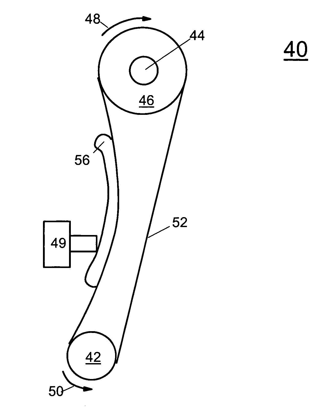
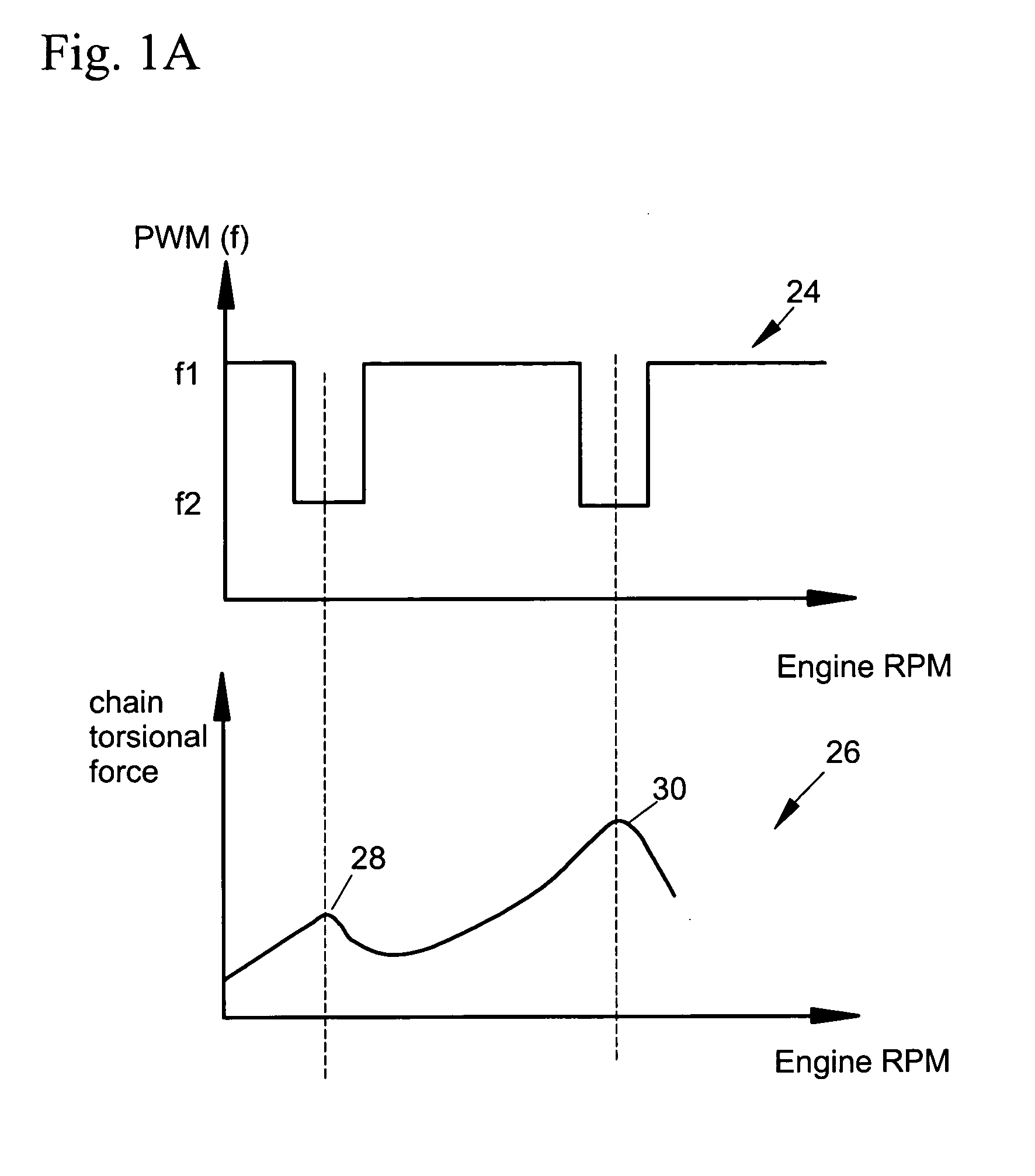
[0030] Timing drives such as modem timing drives with their lower inertia and lower friction develop resonances in and around certain engine speed. The resonance frequency varies with difference engine system due to different distributions of mass of the related parts. The end result is increased load in the timing drive, especially at certain engine speeds or RPMs. The present invention uses a cam phaser for reducing resonance or undue tension of a timing drive.

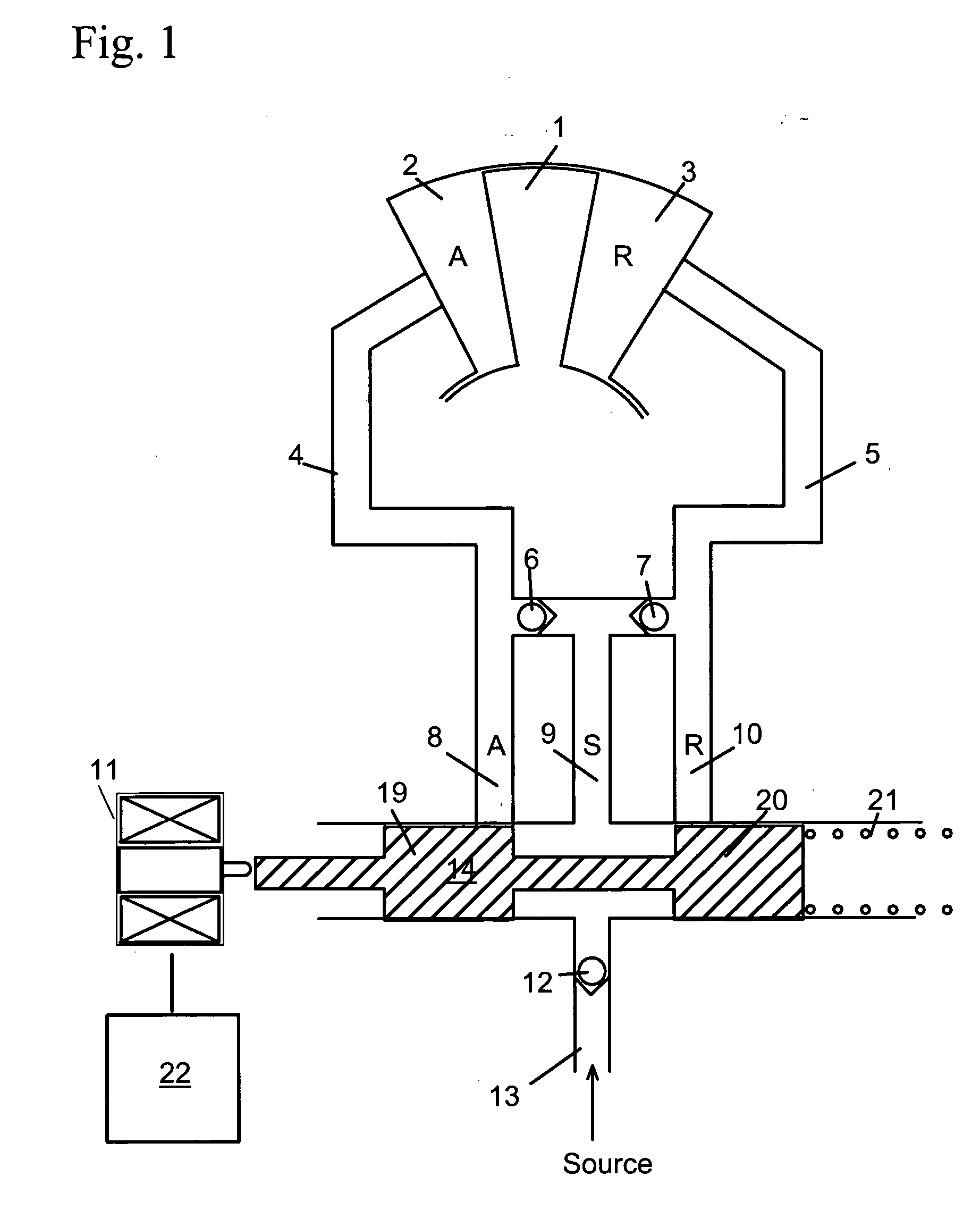
[0031] Referring to FIG. 1, a Cam Torque Actuated (CTA) VCT system is shown. The CTA system uses torque reversals in camshaft caused by the forces of opening and closing engine valves to move vane 1. The control valve in a CTA system allows fluid flow from advance chamber 2 to retard chamber 3 or vice versa, allowing vane 1 to move, or stops flow, locking vane 1 in position. CTA phaser may also have oil input 13 to make up for losses due to leakage, but does not use engine oil pressure to move phaser.

[0032] The operation o...


PUM


Abstract

A chain drive having a phaser such as a hydraulic vane phaser interposed between a timing chain and a driving or driven shaft is provided. The phaser or the vane are controlled to oscillate more at certain engine speeds to thereby reduce the tensioning force on the chain at the certain engine speeds.

Description

REFERENCE TO PROVISIONAL APPLICATION [0001] This application claims an invention which was disclosed in Provisional Application No. 60 / 488,272, filed Jul. 18, 2003, entitled METHOD OF CHANGING THE DUTY CYCLE FREQUENCY OF A PWM SOLENOID ON A CTA CAM PHASER TO INCREASE COMPLIANCE IN A TIMING DRIVE. The benefit under 35 USC §119(e) of the U.S. provisional application is hereby claimed, and the aforementioned application is hereby incorporated herein by reference.FIELD OF THE INVENTION [0002] The invention pertains to the field of variable cam timing (VCT) systems. More particularly, the invention pertains to a method of changing the duty cycle frequency of a PWM solenoid on a cam phaser to increase compliance in a timing drive. BACKGROUND OF THE INVENTION [0003] Traditionally, the camshaft (or, in a multiple camshaft engine, camshafts) of an internal combustion engine, which actuates the intake and / or exhaust valves, is connected to the crankshaft, which receives the force from the pis...

Claims


Application Information

Patent Timeline
Patent Type & Authority Applications(United States)
IPC IPC(8): F02B67/06F01L1/02F01L1/34F01L1/348F01L1/46
CPCF01L1/02F01L1/022F01L1/024Y10T74/2102F01L1/348F01L1/46F01L2820/01F01L1/34
Inventor SIMPSON, ROGER T.
Owner BORGWARNER INC
Why Eureka
Try Eureka