Eureka AIR delivers breakthrough ideas for toughest innovation challenges, trusted by R&D personnel around the world.

Apparatus and process for vaporizing a heavy hydrocarbon feedstock with steam

a technology of heavy hydrocarbon feedstock and apparatus, which is applied in the direction of evaporation, separation processes, hydrocarbon oil treatment products, etc., can solve the problem that the entire construction would require expensive plot spa

Inactive Publication Date: 2005-01-20
SHELL OIL CO
View PDF5 Cites 7 Cited by
  • Summary
  • Abstract
  • Description
  • Claims
  • Application Information

AI Technical Summary

Benefits of technology

In the known mixing nozzles coke may be formed in the flowline, especially at the location where steam is introduced for the final vaporization step. This may eventually result in a diminished passage for liquid and steam in the mixing nozzle, resulting in an increase of the pressure drop over the mixing nozzle. This problem was also addressed in EP-A-95197 and a possible explanation for the coke formation was given therein. The solution to this problem as disclosed in EP-A-95197 involved a specific apparatus comprising a first (inner) tubular element and a second (outer) tubular element surrounding the first tubular element to form an annular space, wherein a first inlet means is provided for introducing a heavy hydrocarbon feedstock into the inner tubular element and a second inlet means is provided for introducing superheated steam into the annular space. The inner tubular element and the outer tubular element are each provided with an open end for the supply of the superheated steam as an annulus around a core of the heavy hydrocarbon feedstock, the open ends terminating in openings arranged in a plane, substantially perpendicular to the longitudinal axes. The apparatus also includes a frusto-conically-shaped element at one end connected to the open end of the second tubular element, provided with a longitudinal axis substantially coinciding with the longitudinal axes of the tubular elements and diverging in a direction away from the outer tubular element. The arrangement of a slightly diverging frusto-conically-shaped element behind the location where the superheated steam meets the heavy hydrocarbon feedstock prevents the contact of liquid droplets with the wall of the element thereby avoiding the risk of coke formation in the apparatus.
After the first introduction of superheated steam, whereby a mixture of steam and liquid feedstock is formed, it is preferred that an annular flow regime is developed in the pipe to the mixing nozzle to fully wet its inner surface and consequently maximize the heat convection efficiency. The annular flow regime should have developed when the feedstock enters the mixing nozzle. The core of the annular flow is formed by vapor containing a mixture of hydrocarbons and steam. The annular flow of feedstock enters the mixing nozzle disclosed in EP-A-95197 in the inner tubular element thereof. In this mixing nozzle a second amount of superheated steam is added to the annular ring surrounding said inner tubular element. The large velocity difference between the steam in this annular ring-shaped confined space between inner and outer tube on the one hand and the liquid annular flow in the inner tube on the other hand creates shear forces and severe hydrocarbon flashing at the point where both flows meet to produce the fine droplet distribution required for mass and heat transfer. The fine droplet distribution will then ensure effective vaporization. The arrangement of a slightly diverging frusto-conically-shaped element behind the location where the superheated steam meets the liquid heavy hydrocarbon feedstock prevents the contact of liquid droplets with the wall of this element thereby avoiding the risk of coke formation in the mixing nozzle itself. Thus, it is important that the steam / liquid mixture entering the mixing nozzle's inner pipe has an annular flow pattern.
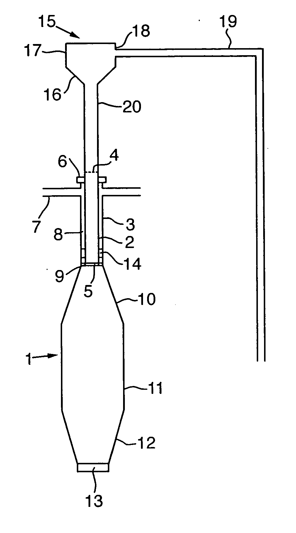
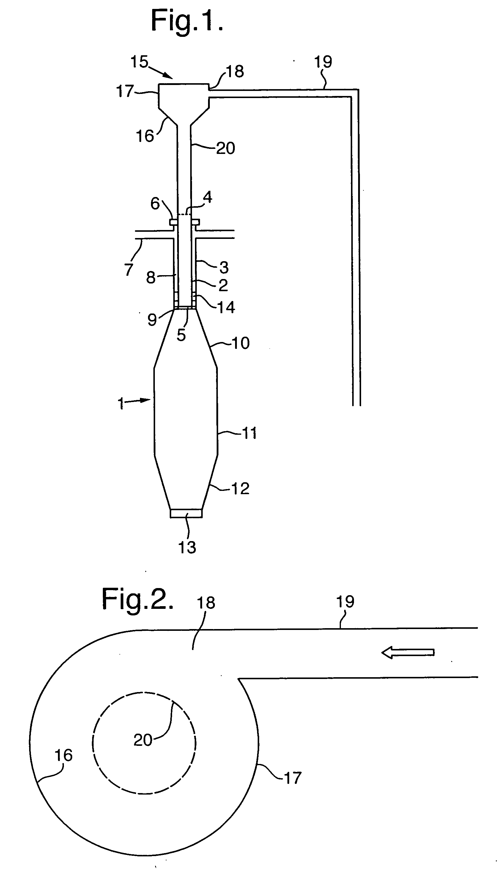
This is effected by using a specific device capable of inducing a gentle swirl pattern to a liquid-containing stream, which device is connected to the feed inlet pipe of the mixing nozzle. This swirl-inducing device will effect bending of the flow direction of the hydrocarbon feedstock with 90° while simultaneously effecting a swirl pattern of the liquid part thereof, thereby forcing the liquid against the wall of the feed inlet pipe extending downwardly to the mixing nozzle with such velocity component perpendicular to the tube's longitudinal axis that an annular flow pattern is re-established.

Problems solved by technology

However, these angles could destroy the annular flow pattern and change it into a slug flow pattern, which is undesired from a heat convection and vaporization point of view.
This would be very uneconomical, because of the higher amount of materials needed to construct the straight pipes and the additional support for these pipes.
Moreover, the entire construction would require expensive plotspace.

Method used


Image

  • Apparatus and process for vaporizing a heavy hydrocarbon feedstock with steam
  • Apparatus and process for vaporizing a heavy hydrocarbon feedstock with steam

Examples


Embodiment Construction

FIG. 1 shows a side-view of a mixing nozzle 1 for supplying superheated steam to a partially vaporized heavy hydrocarbon feedstock for total vaporization thereof. The nozzle 1 comprises an inner, or first, tubular element 2 and an outer, or second, tubular element 3 having coinciding longitudinal axes. The inner tubular element 2 is open at one end to form an outlet 5 for the partially vaporized heavy hydrocarbon feedstock, while the inlet end 4 is connected with a straight feed inlet pipe 20 having the same diameter as the inner tubular element 2. The outer tubular element 3 being open at one end, is closed at the other end by means of a flange 6 welded to the inner tubular element 2. Inlet nozzles 7, being substantially equally distributed over the circumference of the outer tubular element 3, are provided for the supply of superheated steam into an annular space 8 between the inner tubular element 2 and the outer tubular element 3. In order to prevent the occurrence of swirls in ...


PUM

PropertyMeasurementUnit
anglesaaaaaaaaaa
partial pressureaaaaaaaaaa
boilingaaaaaaaaaa

Abstract

Apparatus for the vaporization of a heavy hydrocarbon feedstock with steam includes a frusto-conically-shaped element which is capable of inducing a gentle swirl pattern to a liquid-containing stream, which device is connected to the feed inlet pipe of the mixing nozzle. This swirl-inducing device effects a 90° bending of the flow direction of the hydrocarbon feedstock while simultaneously effecting a swirl pattern of the liquid part thereof, thereby forcing the liquid against the wall of the feed inlet pipe extending downwardly to the mixing nozzle with such velocity component perpendicular to the tube's longitudinal axis that an annular flow pattern is re-established.

Description

The present invention relates to an apparatus and a process for vaporizing a heavy hydrocarbon feedstock with steam. A well-known process for upgrading hydrocarbon feedstock to obtain valuable gaseous (mainly olefins) and liquid products therefrom is the so-called thermal cracking process. To reduce the hydrocarbon partial pressure during the cracking phase, the hydrocarbon feedstock is normally diluted with superheated steam in order to promote the vaporization of the hydrocarbon feedstock, prior to introducing the vaporized hydrocarbon feedstock into the cracking section of a furnace (the radiant section). Such a process is also called steam-cracking. In processing heavy hydrocarbon feedstocks, e.g. materials with a boiling range above 230° C., the vaporization of the liquid material is normally carried out in a plurality of stages. The hydrocarbon feedstock is first preheated, whereafter the still liquid feedstock is admixed with superheated steam to form a two-phase gas / liquid...

Claims


Application Information

Patent Timeline
Patent Type & Authority Applications(United States)
IPC IPC(8): B01D1/14B01D3/38B01J7/02C10G9/14C10G9/36
CPCB01D1/14C10G2300/807C10G2400/20B01D3/38C10G9/36
Inventor CHANDRASEKHARAN, KRISHNAMOORTHYKLOTH, ANTONIUS GIJSBERTUS JOHANNESVAN WESTRENEN, JEROEN
Owner SHELL OIL CO
Why Eureka
Eureka Blog
Learn More