Controlled chest compressor

a chest compression and compressor technology, applied in the field of controlled chest compression, can solve the problems of ineffective and reliably applied for long periods of time, and help achieve the maximum effect of the patient's circulation and breathing, reducing or eliminating any load, and stimulating circulation

Inactive Publication Date: 2005-01-20
WEIL INST OF CRITICAL CARE MEDICINE
View PDF12 Cites 22 Cited by
  • Summary
  • Abstract
  • Description
  • Claims
  • Application Information

AI Technical Summary

Benefits of technology

[0004] In accordance with one embodiment of the present invention, an apparatus is provided for automatically repeatedly applying compressions to the chest of a patient to stimulate circulation and breathing, which is compact in height and which produces deep chest compressions that are closely spaced in time without harming the patient, for maximum effect on the patient's circulation and breathing. The apparatus includes an actuator with a reciprocating member and means for cycling the reciprocating member to alternately apply a downward force to the member to compress the patient's chest, and for applying an upward force to the member to tend to raise it. The cyclic upward force on the member reduces or eliminates any load on the chest that opposes raising of the chest towards it's initial position. The means for raising the reciprocating member can include a spring or pressurized gas. The lower end of the reciprocating member can be adhered to the patient's chest, as through contact adhesive or a vacuum device, to actually pull up on the chest.

Problems solved by technology

Chest compressions applied by hand are helpful, but are generally not as effective, or as reliably applied for long periods of time, as chest compressions applied cyclically by an automatic device.

Method used


Image

  • Controlled chest compressor
  • Controlled chest compressor
  • Controlled chest compressor

Examples


Embodiment Construction

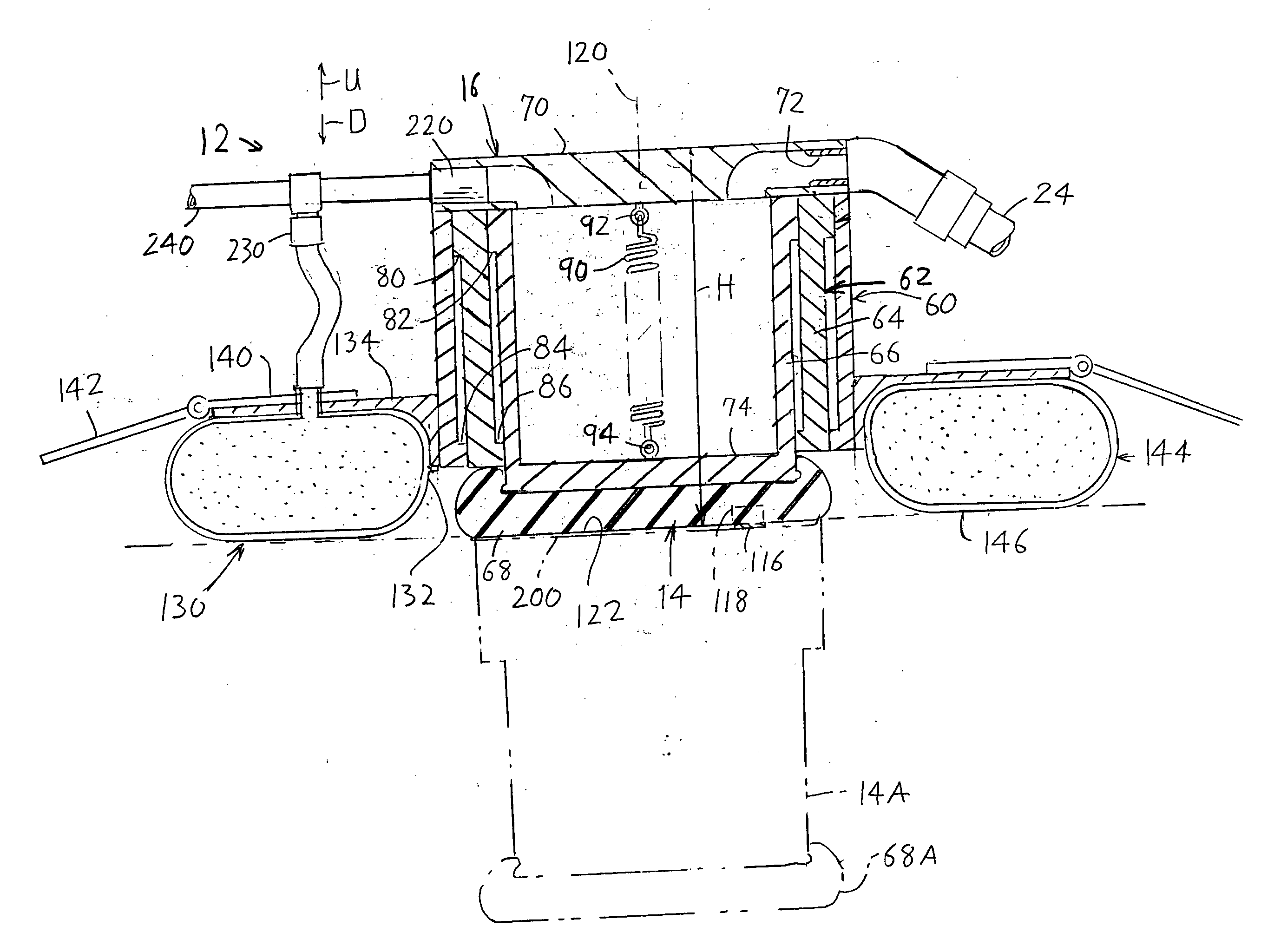
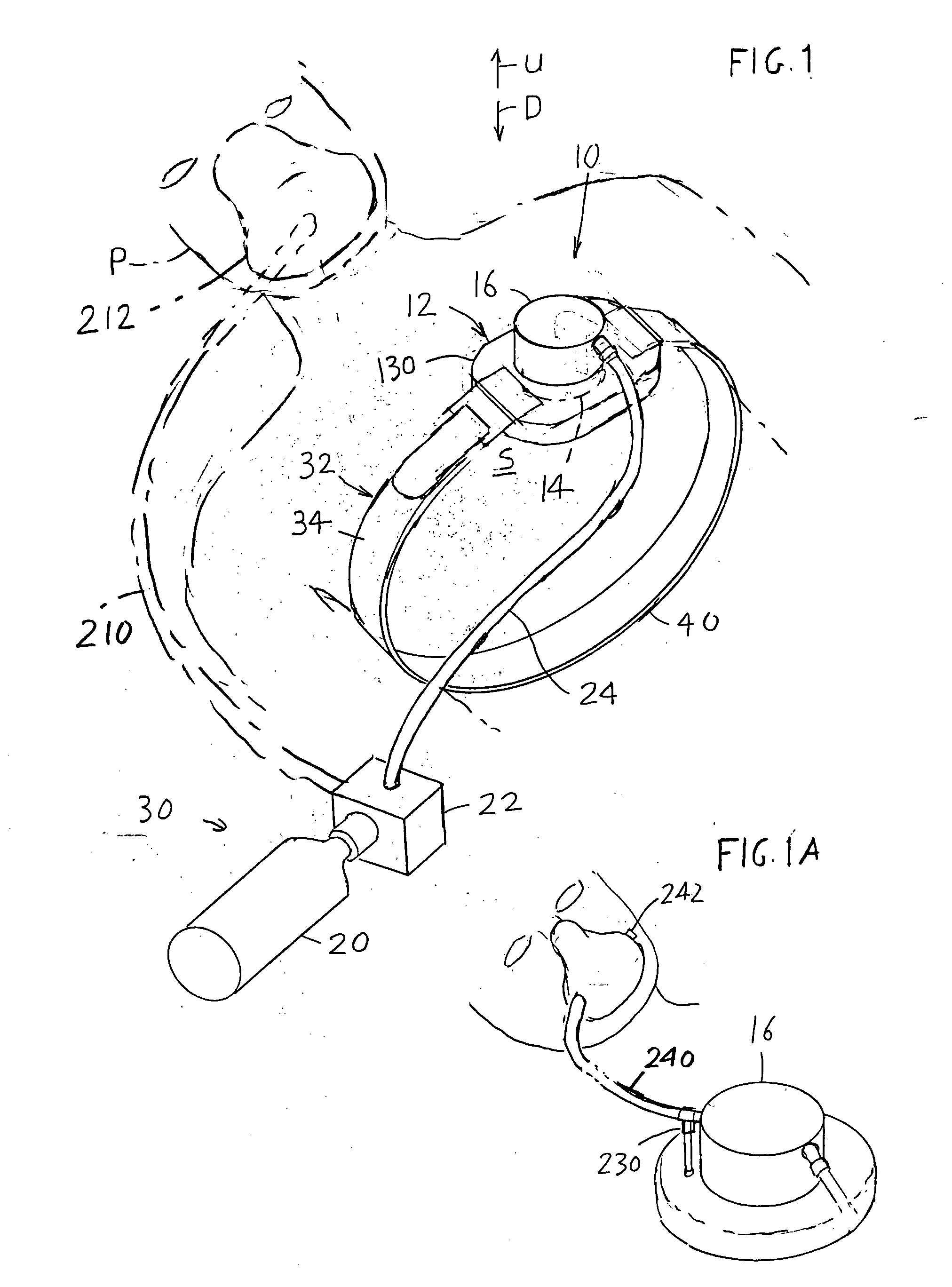
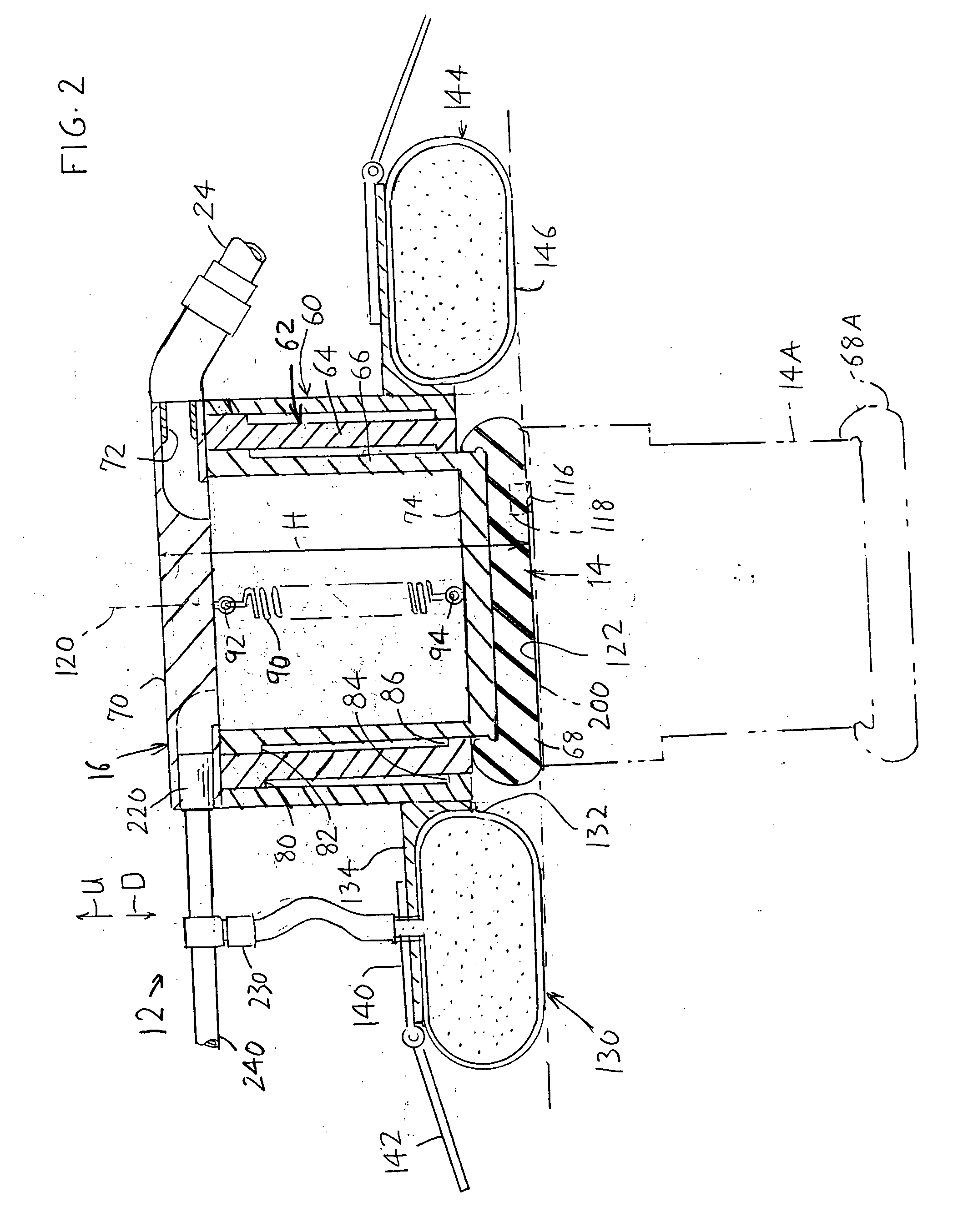
[0015]FIG. 1 illustrates a patient P who has dangerously low blood circulation such as might occur in a heart attack. An apparatus 10 of the invention includes a compressor assembly 12 with a reciprocating member 14 having a diameter of about 3 to 4 inches, which can be forcefully pushed down against the sternum S of the patient's chest in a series of regular pulses. The chest compressions stimulate the heart of the patient, which may cause a stopped heart to start again. The compressions also cause some circulation of blood, and also cause some breathing of the patient to supply oxygen to the bloodstream. For an adult male patient, depressing member 14 can press down with a maximum force of about 100 to 120 pounds, in pulses spaced by perhaps ½ to 1 second apart. The period of each cycle is no more than about 1 second (i.e. less than two seconds). This mimics the chest compressions applied manually in CPR (cardiopulmonary resuscitation). For a child, the force is lower. The downwar...


PUM


Abstract

Apparatus for repeatedly compressing the chest of a patient to stimulate blood circulation and breathing, includes an energizable actuator (16) that repeatedly presses against the patient's chest, a torso wrap (32) that wraps to the back of the patient, and a stabilizer (130) that minimizes tilt of the actuator. The stabilizer is generally in the form of an inflatable toroid, or foam toroid, which extends substantially completely around the actuator to prevent tilting in any direction. The actuator includes a reciprocating member (14) that is not only moved down to compress the chest, but that is also pushed up to allow the chest to rise more rapidly. A pressing member (68) at the bottom of the reciprocating member, can tilt. The means for cycling includes compressed breathing gas for cyclically pushing down the reciprocating member, the actuator exhaust being delivered to the patient for breathing. Chest compression and chest recovery, respectively occupy under 30%, and over 70% of the duration of each cycle.

Description

BACKGROUND OF THE INVENTION [0001] Many persons who suddenly become unconscious can be revived by applying chest compressions to stimulate blood circulation and breathing. Shocks applied by defibrillators can sometimes shock the heart into beating again. Chest compressions applied by hand are helpful, but are generally not as effective, or as reliably applied for long periods of time, as chest compressions applied cyclically by an automatic device. An automatic device can continue chest compressions while defibrillator shocks are applied and while the patient is loaded onto a stretcher and carried to an ambulance, and enables continued chest compressions while the patient travels in the ambulance even when other patients are in the ambulance who require the attention of a rescuer. [0002] Ambulances are often constructed with a plurality of stretcher holders or bays stacked on one another, to hold a plurality of patients who may be injured in a single disaster. Any apparatus that app...

Claims


Application Information

Patent Timeline
Patent Type & Authority Applications(United States)
IPC IPC(8): A61H9/00A61H31/00
CPCA61H9/0071A61H31/006A61H2031/003A61M2202/0208A61M16/06A61M16/10A61H2201/1238
Inventor WELL, MAX HARRYBISERA, JOEYOUNG, CLAYTONCASTILLO, CARLOST
Owner WEIL INST OF CRITICAL CARE MEDICINE
Why Eureka
Try Eureka