Seal system for irrigated scrubber mandrel assembly

a scrubber and mandrel technology, applied in the field of substrate preparation systems and methods, to achieve the effect of minimizing the hydraulic pressure of the input cleaning fluid, minimizing the pressure on the end of the mandrel, and simple and economic solution

Inactive Publication Date: 2005-01-27
XYRATEX TECH LTD
View PDF2 Cites 6 Cited by
  • Summary
  • Abstract
  • Description
  • Claims
  • Application Information

AI Technical Summary

Benefits of technology

[0009] The present invention provides a simple and economic solution to the particulates contribution problem in the art by a brush core water supply housing assembly in which a sliding piston inside the housing is configured with a flange having one or more recesses so that the piston is out of contact with the rotating part of the brush core mandrel bearing assembly. Rather, the piston has a specially configured flange that has an outer face that only contacts the stationary outer race of the mandrel bearing. The water supply piston is also configured with a full bore, that is, without a reduced bore forming a nozzle, thereby minimizing the hydraulic pressure of the input cleaning fluid so as to minimize the pressure on the end of the mandrel. In addition, a tolerance-controlled leak through the bearing is provided by the configuration of the outer, stepped face of the piston flange. This leak provides a flushing of the area in which wear might be a source of particle generation. Further, this controlled leak is upstream of the brush core apertures, originates adjacent the potential wear faces and exits external to the brush upstream of it. In combination, these features function to substantially eliminate both the source of particle generation from contact wear between brush core mandrel and cleaning / rinsing fluid supply housing, and the contribution of such wear particles into the interface between the brush and the substrate surface being cleaned.

Problems solved by technology

This leak provides a flushing of the area in which wear might be a source of particle generation.
Further, this controlled leak is upstream of the brush core apertures, originates adjacent the potential wear faces and exits external to the brush upstream of it.

Method used


Image

  • Seal system for irrigated scrubber mandrel assembly
  • Seal system for irrigated scrubber mandrel assembly
  • Seal system for irrigated scrubber mandrel assembly

Examples


Embodiment Construction

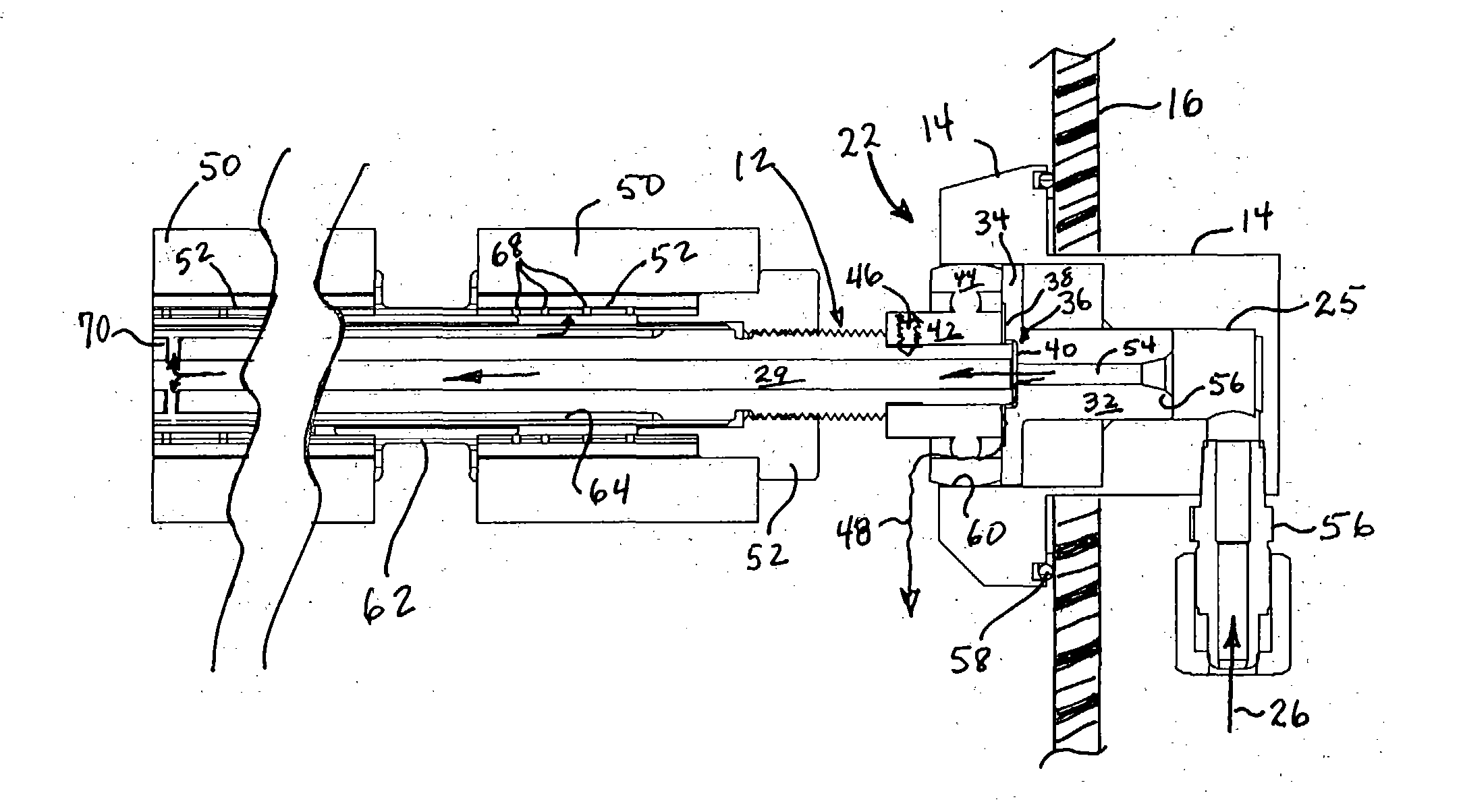
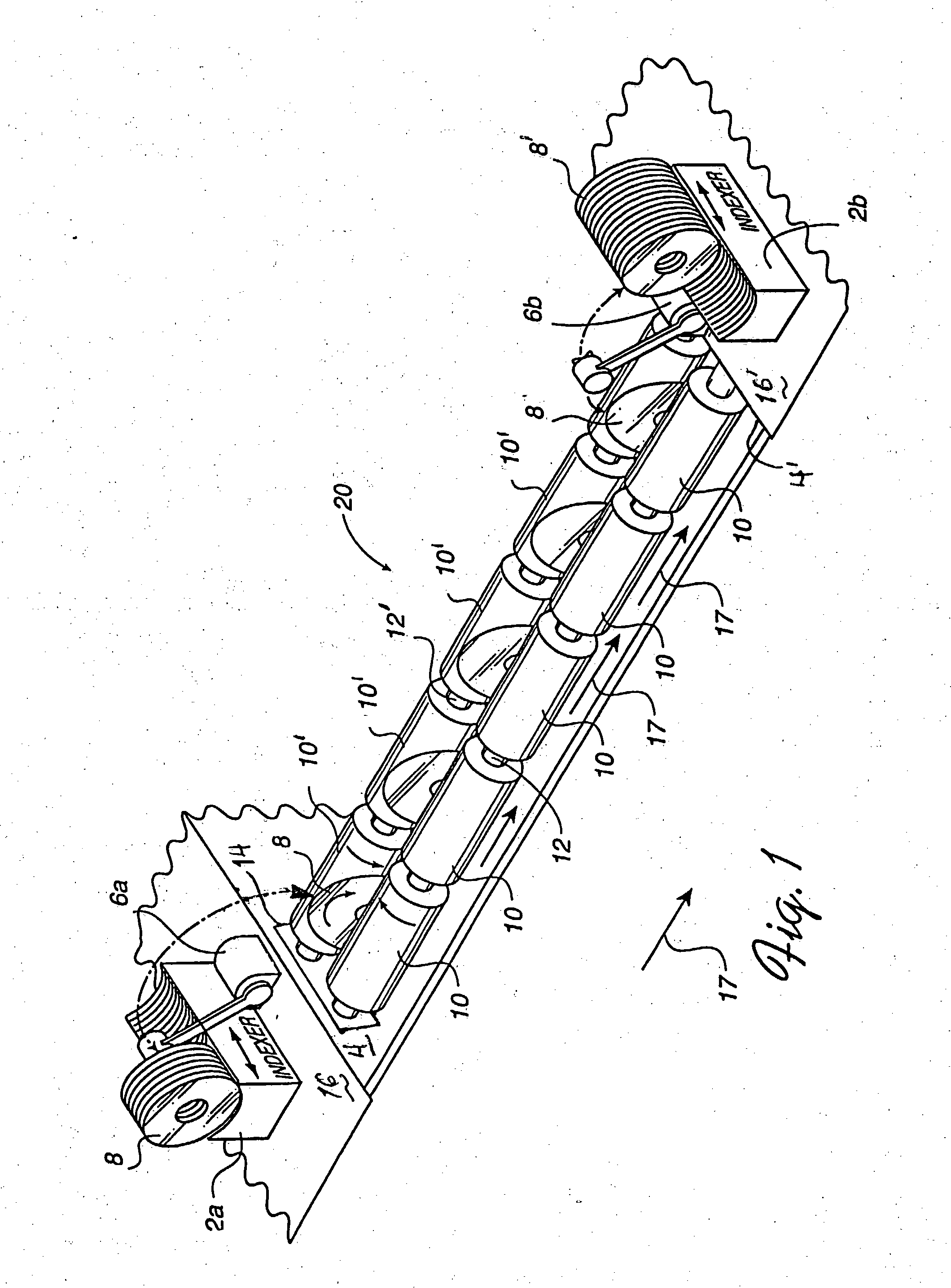
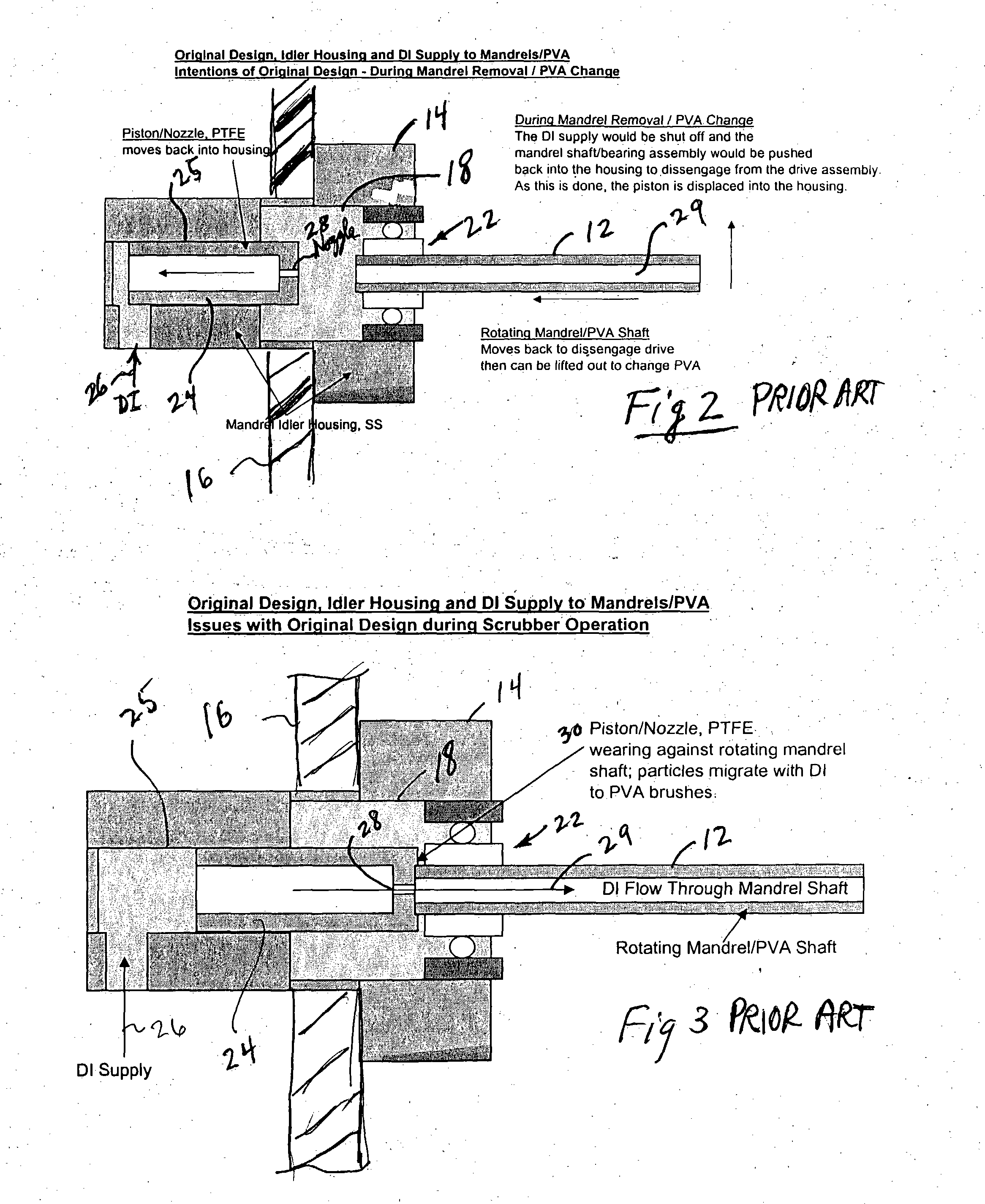
[0017] The following detailed description illustrates the invention by way of example, not by way of limitation of the scope, equivalents or principles of the invention. This description will clearly enable one skilled in the art to make and use the invention, and describes several embodiments, adaptations, variations, alternatives and uses of the invention, including what is presently believed to be the best modes of carrying out the invention.

[0018] In this regard, the invention is illustrated in the several figures, and is of sufficient complexity that the many parts, interrelationships, and sub-combinations thereof simply cannot be fully illustrated in a single patent-type drawing. For clarity and conciseness, several of the drawings show in schematic, or omit, parts that are not essential in that drawing to a description of a particular feature, aspect or principle of the invention being disclosed. Thus, the best mode embodiment of one feature may be shown in one drawing, and ...


PUM

PropertyMeasurementUnit
sizeaaaaaaaaaa
pressureaaaaaaaaaa
diameteraaaaaaaaaa

Abstract

An improved cleaning fluid supply housing assembly for a cascade-type substrate scrubber having a sliding piston configured with a flange with recesses so that the piston is out of contact with the rotating part of the brush core mandrel bearing assembly. Rather, the piston flange outer face only contacts the stationary outer race of the mandrel bearing. The water supply piston is also configured with a full bore to minimize the pressure on the end of the mandrel. A tolerance-controlled leak through the bearing is provided by the configuration of the piston flange to provide a flushing of the area in which wear might be a source of particle generation by a controlled tolerance leak upstream of the brushes. These features substantially eliminate the source of particle generation from contact wear and the contribution of such wear particles into the interface between the brush and the substrate surface being cleaned.

Description

CROSS REFERENCE TO RELATED APPLICATIONS [0001] This application is related to regular U.S. application Ser. No. 09 / 580,827 filed May 26, 2000 by David T. Frost et al, entitled DISK CASCADE SCRUBBER, which in turn is based on Ser. No. 60 / 136,635 filed May 27, 1999 and Ser. No. 60 / 154,070 filed Sep. 20, 1999, all of which applications and this one have a common assignee. The subject matter of that application is hereby incorporated by reference as if reproduced here, and the benefit of the filing dates of the aforesaid applications is hereby claimed under 35 US Code §§ 119 and 120.FIELD [0002] This invention is directed to substrate preparation systems and methods, and more particularly to apparatus and methods for cleaning of disk-shaped substrates, including silicon wafers of the type used in the fabrication of computer chips, and aluminum, ceramic, plastic, glass and multi-component disks for data storage devices such as hard disk drives (HDD), compact discs (CD), digital video dis...

Claims


Application Information

Patent Timeline
Patent Type & Authority Applications(United States)
IPC IPC(8): B08B1/02B08B1/04G11B23/50H01L21/00
CPCB08B1/02H01L21/67046G11B23/505B08B1/04
Inventor HARBISON, ADAM SEANPETERSON, SCOTTRILEY, BRYAN
Owner XYRATEX TECH LTD
Why Eureka
Try Eureka