Moisture-resistant floor tile covering system for concrete floors

a floor tile and concrete technology, applied in the field of floor tile covering systems for concrete floors, to achieve the effect of avoiding or substantially reducing

Inactive Publication Date: 2005-01-27
JANESKY LAWRENCE M
View PDF8 Cites 29 Cited by
  • Summary
  • Abstract
  • Description
  • Claims
  • Application Information

AI Technical Summary

Benefits of technology

[0008] The present invention relates to a water-resistant flooring system for insulating against dampness and cold penetration from concrete sub-floors, and which will not be damaged by water penetration from any direction or source, including above-floor plumbing problems or flooding.
[0009] The present flooring system comprises a thermally-insulating water-vapor-proof, air-gap, solid plastic barrier tile layer system comprising a strong rigid flat solid layer of water-resistant plastic, such as ABS, polyvinyl chloride, polyethylene, polypropylene or polycarbonate, which is either molded with integral spaced plastic legs or spacers such as studs or slots or other raised areas on the underside thereof, or is laminated or bonded to a separate water-resistant solid plastic barrier sheet which is molded with integral spaced plastic legs or spacers such as studs or slots or other raised and / or depressed areas on the underside thereof, to provide spaced leg portions which contact the surface of the concrete floor and which space and support the underside of the flat plastic tile from the surface of the concrete floor to provide an insulating thermal air gap barrier space between about ⅛″ and 1″ high, preferably about {fraction (3 / 8)} inch high, to admit and circulate any water vapor penetrating up through the concrete floor beneath the entire barrier tile layer system. The air gap barrier space provides a space network within which the water vapor circulates and comes into equilibrium with the water content of the porous concrete floor. Water condensation, which will occur if you lay a flat sheet of plastic against a concrete floor, is avoided or substantially reduced by the present plurality of spacers which create the air gap barrier space. Water vapor from the concrete floor cannot condense within the air gap, and humid air from the basement living space cannot penetrate the interlocked plastic tiles to condense on the concrete floor.

Problems solved by technology

Water vapor from the concrete floor cannot condense within the air gap, and humid air from the basement living space cannot penetrate the interlocked plastic tiles to condense on the concrete floor.

Method used


Image

  • Moisture-resistant floor tile covering system for concrete floors
  • Moisture-resistant floor tile covering system for concrete floors
  • Moisture-resistant floor tile covering system for concrete floors

Examples


Embodiment Construction

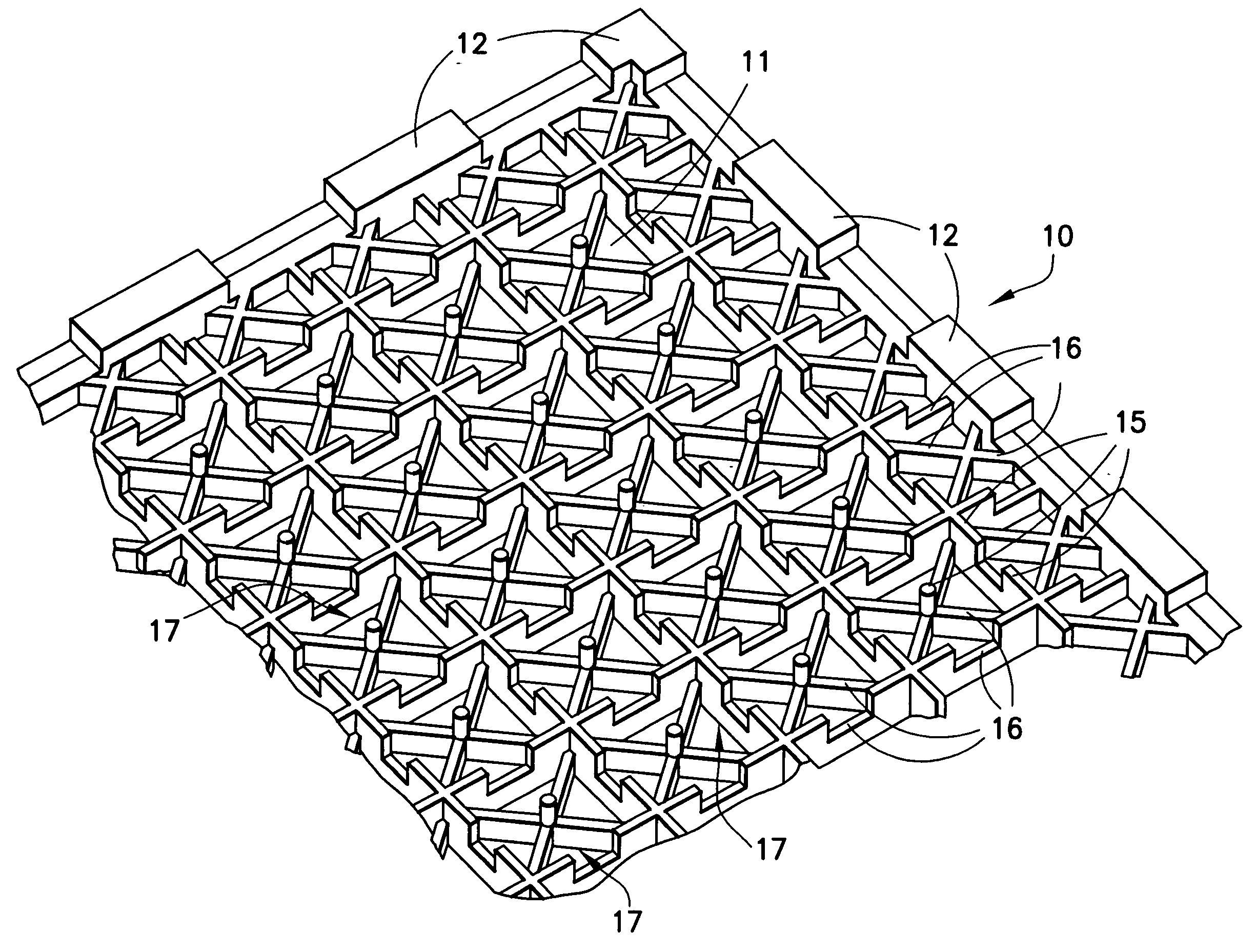
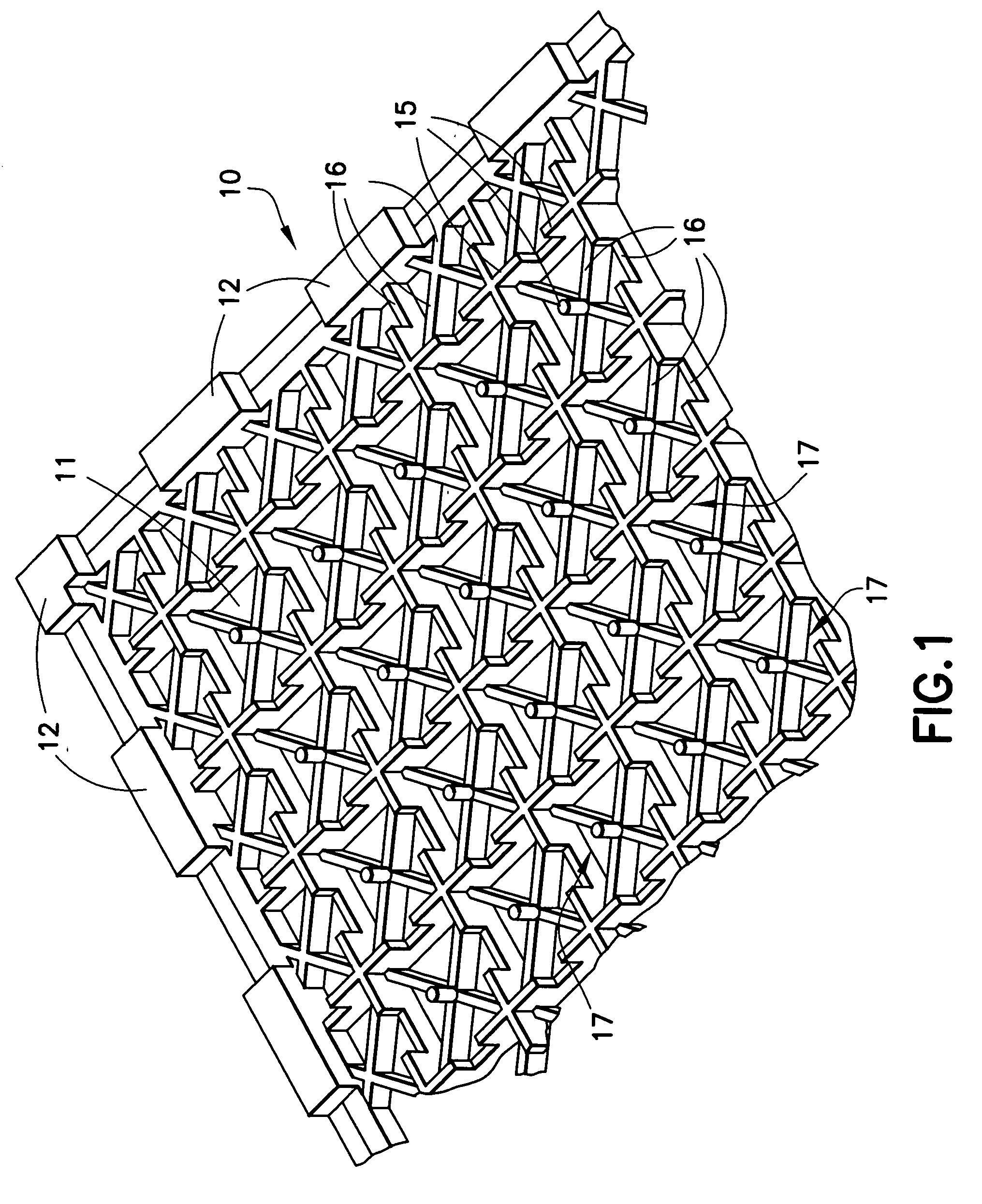
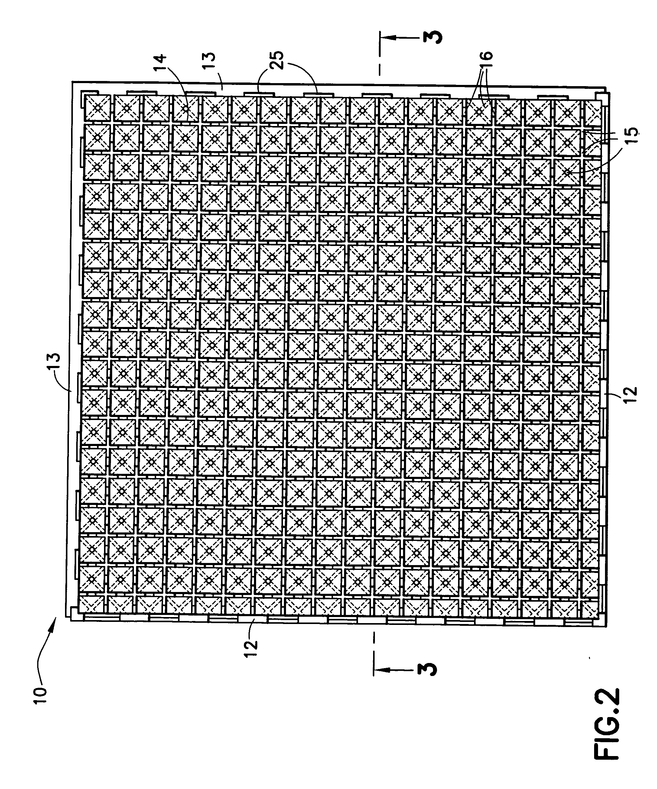
[0017] Referring to FIG. 1, the underside 11 of a corner section of a solid water-resistant plastic floor tile 10 is illustrated, the tile 10 having groove or slot means 12 along two edges thereof and tongue means 13 along the other two edges, as shown in FIGS. 2 and 3, for mating with corresponding complementary means on adjacent tiles to lock the tiles to each other and produce a substantially-continuous, smooth plastic floor surface which is water impervious.

[0018] The plastic tile 10 of FIGS. 1 to 3 is molded to have integral spaced plastic support studs or legs or wall sections 15 projecting a maximum distance from the underside 11 thereof, and intermediate plastic network sections 16 of intermediate height. The legs or wall sections 15 project down a uniform distance to contact the concrete floor 11, a distance of about {fraction (5 / 16)}″, to form an interconnected insulation airspace image network 17 between the upper surface of the concrete floor and the underside of the ne...


PUM

PropertyMeasurementUnit
thicknessaaaaaaaaaa
thermal breakaaaaaaaaaa
heat conductionaaaaaaaaaa

Abstract

A thermally insulating tile floor covering system comprising a water resistant, inorganic, thermal air-gap plastic barrier tile layer which is provided with a network of integral spaced plastic studs, legs or wall sections on the underside thereof, to form an interconnected space network between the undersurface of the flat plastic tile and the surface of a concrete floor supporting the tile. The space network provides an insulating thermal air gap barrier space to receive and circulate any water vapor penetrating up through the concrete floor.

Description

BACKGROUND OF THE INVENTION [0001] 1. Field of the Invention [0002] The present invention relates to an improved system for protecting finished flooring over on-grade concrete floors from damage from water vapor penetration and for insulating them from the cool earth temperatures. Concrete floors particularly concrete floors installed or poured over the dirt surfaces of sub-terrainean rooms such as basement living spaces of homes or the ground-level rooms or work spaces of slab-homes or buildings, are particularly susceptible to water vapor penetration. Conventionally, such concrete floors are covered with plastic tiles or carpeting to improve their appearance and make them more comfortable to the feel. [0003] However, concrete floors are relatively porous and also conduct the cold temperature of the ground, which can result in water vapor penetration and condensation at the interior surface of the concrete floor, causing separation of floor tiles adhered thereto or causing a moistu...

Claims


Application Information

Patent Timeline
Patent Type & Authority Applications(United States)
IPC IPC(8): A01K1/015A47G27/02E04F15/02E04F15/10
CPCA01K1/0151E04F15/10E04F15/02A47G27/0293E04F15/02194E04F15/105
Inventor JANESKY, LAWRENCE M.
Owner JANESKY LAWRENCE M
Why Eureka
Try Eureka